
Circuit Diagram
Index 1378
FREEZER_MELTDOWN_ALARM
Published:2009/6/23 1:29:00 Author:May

The meltdown is a magnet held to a small stand by ice. A reed switch is below the magnet. When the ice melts, the magnet falls on the switch, closing it, and completing the alarm circuit. (View)
View full Circuit Diagram | Comments | Reading(659)
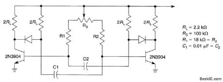
QUADRATURE_WAVE_OSCILLATOR
Published:2009/6/23 1:49:00 Author:Jessie


By using a high-frequency quad current-feedback amplifier (the HA5025) as an RC oscillator, four quadrature sine waves can be generated. The HA5025's four separate amplifiers generate the sine waves, and the quad NAND gate, U2, is biased at its threshold, so it acts as a sine-wave to square-wave converter when the she waves are ac coupled into its input. (View)
View full Circuit Diagram | Comments | Reading(1223)
Liquid level automatic controller circuit diagram 6
Published:2011/7/28 20:40:00 Author:Ecco | Keyword: Liquid level , automatic controller

The liquid level automatic controller circuit is composed of the power supply circuit, level detection circuit and control implementation circuit, and the circuit is shown as the chart. Power supply circuit is composed of the knife switch Q, fuse FU, power transformer T, rectifier diodes VD1 ~ VD4, current limiting resistors R1 and R5, filter capacitor C1 and Zener diode VS. Level detection circuit is composed of the high-level electrode H, low-level electrode L and the main electrode M. Control implementation circuit is composed of the transistor V, relay K, time-base integrated circuit IC, diodes VD5 ~ VD8 and external RC components.
(View)
View full Circuit Diagram | Comments | Reading(1085)
SUBAUDIBLE_TONE_ENCODER
Published:2009/6/23 1:48:00 Author:Jessie

This twin-T oscillator produces six preset subaudible tones from 93 to 170 Hz in three ranges. (View)
View full Circuit Diagram | Comments | Reading(0)
SUN_POWERED_ALARM
Published:2009/6/23 1:29:00 Author:May

Circuit turns on when light (sunlight) strikes photocell. Potentiometer R sets light level at which the alarm sounds. Painted tube (black on inside) may be used on photocell to aim at the sun. (View)
View full Circuit Diagram | Comments | Reading(756)
DIRECT_CONVERSION_7_MHz_RECEIVER
Published:2009/6/23 Author:May

An NE602 is used to mix signals in the 7-MFlz range with an LO and to produce audio output. (View)
View full Circuit Diagram | Comments | Reading(1444)
Temperature controller circuit diagram 2
Published:2011/7/28 21:37:00 Author:Ecco | Keyword: Temperature controller

The temperature controller circuit is composed of the power supply circuit, temperature detection circuit, reference voltage circuit, temperature indicator circuit, voltage comparator amplifier and control implementation circuit, and it is shown as the chart. Power supply circuit is composed of the power switch S, power transformer T, bridge rectifier UR, filter capacitors C1, C2, three-terminal voltage regulator integrated circuit IC2, current limiting resistor RIO and power indicator LED VL1. Temperature detection circuit consists of the transistor temperature sensor V1, resistor R1, capacitor C3 and N1 which is inside of the operational amplifier integrated circuit IC1 (N1 ~ N4).
(View)
View full Circuit Diagram | Comments | Reading(1438)
DIFFERENTIAL_VOLTAGE_TO_CURRENT_CONVERTER
Published:2009/6/23 Author:May

View full Circuit Diagram | Comments | Reading(1097)
Temperature controller circuit diagram 5
Published:2011/7/28 21:46:00 Author:Ecco | Keyword: Temperature controller

The temperature control circuit is composed of the power supply circuit, temperature detection control circuit and control implementation circuit, and it is shown as the chart. Power supply circuit is composed of the power transformer T, rectifier diodes VD1 ~ VD4, resistors R1 and R2, power indicator LED VL1, filter capacitor C1 and Zener VS and so on. Temperature detection control circuit consists of thermistor RT, time-base integrated circuit IC, potentiometers RP1 ~ RP4, resistor R3 and capacitors C2 ~ C4. Control implementation circuit is composed of the relay K1, LED VL2, diode VD5, AC contactor KM and electric heater EH.
(View)
View full Circuit Diagram | Comments | Reading(816)
LATCHING_BURGLAR_ALARM_1
Published:2009/6/22 23:58:00 Author:May

Closing the Protective circuit(i.e.,R1 to R2) applies positive voltage to the gate ofSCR1 and sounds the alapy). It can only be turned of with S1. (View)
View full Circuit Diagram | Comments | Reading(776)
SYNC_TO_ASYNC_CONVERTER
Published:2009/6/22 23:58:00 Author:May

This simple converter donsists of two ICs and a voltage regulator. The Sipex MAS7838, which acts as the converter, selects the conversion speed to that of the synchronized data clock. It has intemal switches and registers to perform the async-to-sync, or sync-to-async, conversion. The Maxim MAX238 provides the RS-232 drivers and receivers for interfacing with the data bus. These chips require a 5-Vdc power supply; a generic 78L05 reduces the +12V at the DB25 pin 9 to the +5V needed. A crystal fre-quency of 4.91MHz is suitable for convetting to 19.2 kbits or a sub-multiple (9.6, 4.8, 2.4, etc.). Two 1N4001 diodes protect the extemal RTS (ready to send) control circuitry if the RTS is enabled by S1.When JP1 is removed, the converter is transparent in the sync mocte and no conversion will occur.The completed unit is mounted atop a universal breakout adapter, and the control lines are jumpered according to the chart in the figure. The physical size is approximately 1 x 2.25 x 2.5 inches and will easily plug into the DB25 socket on a synchronized data communications equipment (DCE) communication device. (View)
View full Circuit Diagram | Comments | Reading(1689)
GATED_2_kHz_BUZZER
Published:2009/6/22 23:56:00 Author:May

View full Circuit Diagram | Comments | Reading(601)
5_V,5_A_STEP_DOWN_CONVERTER
Published:2009/6/22 23:56:00 Author:May


This circuit is useful where power must be distributed by a higher (10 to 60 V) bus. The circuit reduces power dissipation and elintinates inefficient passive linear regulators. The switching fre-quency is in the 100-kHz region. (View)
View full Circuit Diagram | Comments | Reading(778)
SCR_CONVERTER
Published:2009/6/22 23:55:00 Author:May

Two SCR devices are used in a push-pull driver to convert 28 Vdc to 155 Vdc, using the transformer and bridge shown. A center-tapped transformer with 24 V:120 V could be used for 60-Hz applications. The trigger circuit supplies a push-pull drive signal. (View)
View full Circuit Diagram | Comments | Reading(1595)
Temperature controller circuit diagram 3
Published:2011/7/28 21:41:00 Author:Ecco | Keyword: Temperature controller

The temperature controller circuit is composed of the power supply circuit and temperature detection control circuit, and it is shown as the chart. Power supply circuit is composed of the power switch S, fuse FU, power transformer T, rectifier diodes VD1, VD2 and filter capacitor C. Temperature detection control circuit is composed of electric contact thermometer Q, relay K, AC contactor KM, diode VD3 and electric heater EH. C selects the aluminum electrolytic capacitor with the voltage in 25V. VD1 ~ VD3 select the 1 N4007 silicon rectifier diodes. K selects the JRX-13F orJQX-4F 12V DC relay.
(View)
View full Circuit Diagram | Comments | Reading(556)
BURGLAR_ALARM
Published:2009/6/22 23:55:00 Author:May

View full Circuit Diagram | Comments | Reading(1171)
SIMPLE_VARIABLE_FREQUENCY_OSCILLATOR
Published:2009/6/22 23:55:00 Author:May
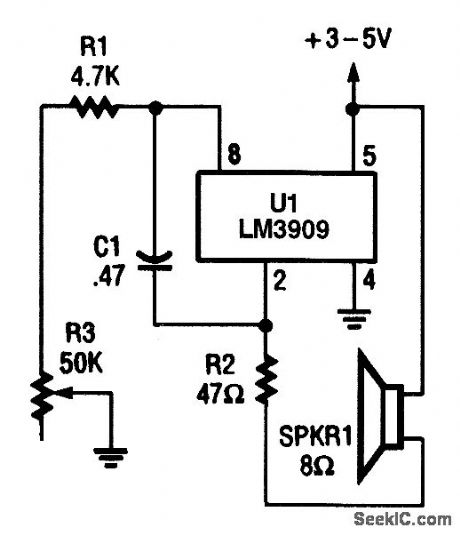


In this variable audio frequency oscillator, the output of U1 at pin 2 is used to drive an 8-Ω speaker through R2 (which functions as a current-limiter). (View)
View full Circuit Diagram | Comments | Reading(783)
PIEZOELECTRIC_ALARM
Published:2009/6/22 23:54:00 Author:May

View full Circuit Diagram | Comments | Reading(0)
VARIABLE_DUTY_CYCLE_FROM_ASTABLE
Published:2009/6/22 23:54:00 Author:May
If R1=R2=R3 and C1=C2=C3If potentiometer R3 is set at N%of rotation,thenTTOTAL≈0.7[(R+NR3)C+[R+[1-N)R3C]TTOTAL≈1.4 (R+R3)C and the duty Cycle can be varied without changing frequency. (View)
View full Circuit Diagram | Comments | Reading(841)
FET_QUARTZ_CRYSTAL_OSCILLATOR
Published:2009/6/23 1:48:00 Author:Jessie

This oscillator uses an MPF102 JFET as an active element. (View)
View full Circuit Diagram | Comments | Reading(4191)
| Pages:1378/2234 At 2013611362136313641365136613671368136913701371137213731374137513761377137813791380Under 20 |
Circuit Categories
power supply circuit
Amplifier Circuit
Basic Circuit
LED and Light Circuit
Sensor Circuit
Signal Processing
Electrical Equipment Circuit
Control Circuit
Remote Control Circuit
A/D-D/A Converter Circuit
Audio Circuit
Measuring and Test Circuit
Communication Circuit
Computer-Related Circuit
555 Circuit
Automotive Circuit
Repairing Circuit