
Circuit Diagram
Index 1377
IN_LINE_WATTMETER
Published:2009/6/23 1:34:00 Author:May

The circuit is not frequency sensitive. Its calibration will be accurate over a wide fre-quency spectrum, such as the entire amateur hf spectrum, if the values of L2, the voltage di-vider capacitors C1-2 and C3, and the resis-tances of RI-2 are chosen properly. R1-2 and CR1-2 should be matched for best results.Generally, R1-2 must be small compared to the reactance of L2 so as to avoid any significant effect on the L2 current which is induced by the transmission line current flowing through L1. The lower frequency limit of the bridge is set by the RI-R2/Ls ratio, and the cutoff is at the point where the value of RI-R2 becomes significant with reference to the reactance of L2 at that frequency point. (View)
View full Circuit Diagram | Comments | Reading(778)
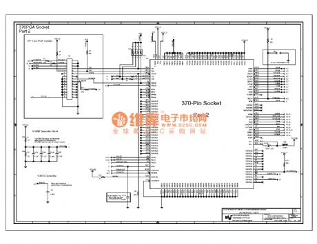
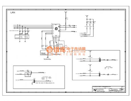
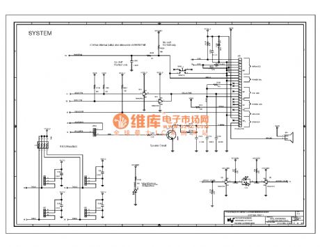
Computer motherboard circuit diagram 810 1_03
Published:2011/7/28 20:29:00 Author:Ecco | Keyword: Computer motherboard
View full Circuit Diagram | Comments | Reading(412)
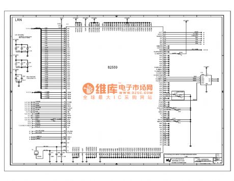
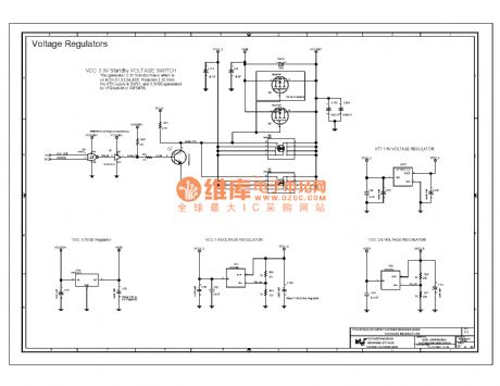
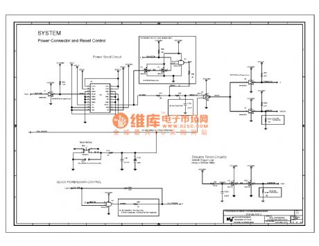
Computer motherboard circuit diagram 810 1_04
Published:2011/7/28 20:30:00 Author:Ecco | Keyword: Computer motherboard
View full Circuit Diagram | Comments | Reading(472)
LOGIC_GATE_SINE_WAVE_OSCILLATOR
Published:2009/6/23 1:34:00 Author:May
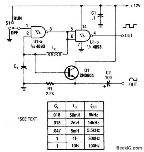
An inductor and capacitor are used here as frequency-determining elements in an LC oscillator. (View)
View full Circuit Diagram | Comments | Reading(872)
WIEN_BRIDGE_OSCILLATOR_II
Published:2009/6/23 1:33:00 Author:May

The operating frequency of this Wien-bridge oscillator is determined by C1, C2, R1, and R2. It can easily be modified to act as a tunable oscillator by substituting a dual-gang linear potentiometer for R1 and R2. (View)
View full Circuit Diagram | Comments | Reading(577)
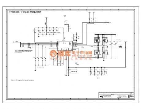
Computer motherboard circuit diagram 810 1_27
Published:2011/7/27 21:04:00 Author:Ecco | Keyword: Computer motherboard
View full Circuit Diagram | Comments | Reading(545)
STABILIZED_WIEN_BRIDGE_OSCILLATOR
Published:2009/6/23 1:50:00 Author:Jessie

In this application, the AD534 is used as a vari-able-gain amplifier for the feedback signal from the output to the Y input, via the Wien bridge. The peak-rectifter and filter combination applies sufficient voltage to the X (denominator) input to maintain a stable oscillation-amplitude (with about 0.2% ripple). At startup, because X is small (divider mode), the gain is high, and the oscillation builds up rapidly. This is but one of several possible schemes, involving no extemal active elerrtents. Its forte is simplicity, rather than high performance; nevertheless, the amplitude is not greatly affected by supply and temperature variations, about 0.003 dB per volt, and 0.005 dB per degree. (View)
View full Circuit Diagram | Comments | Reading(1640)
RF_POWER_METER
Published:2009/6/23 1:32:00 Author:May
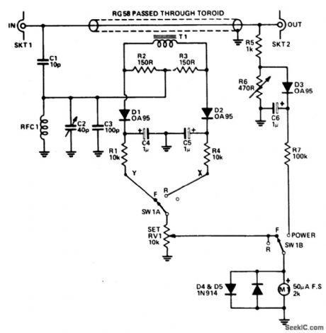
Reflectometer (SWR Power Meter) covers three decades-from 100 kHz to100 MHz. It can be constructed for rf powers as low as 500 mW or up to 500 watts. (View)
View full Circuit Diagram | Comments | Reading(6131)
Computer motherboard circuit diagram 810 1_28
Published:2011/7/27 21:04:00 Author:Ecco | Keyword: Computer motherboard
View full Circuit Diagram | Comments | Reading(496)
UJT_100_kHz_CALIBRATION_OSCILLATOR
Published:2009/6/23 1:49:00 Author:Jessie

This unusual 100-kHz oscillator (whose fre-quency is determined by XTALl) can be used as a marker generator to calibrate the analog diai of a communication receiver, or its output can be fed to a divider courtter to produce a stable lower-fre-quency output for use as a clock-signal generator. (View)
View full Circuit Diagram | Comments | Reading(1911)
AUDIO_MIXER
Published:2009/6/23 1:49:00 Author:Jessie

The 741 op amp is used as a summing amplifier to combine several audio inputs. Overall gain is set by Rf. (View)
View full Circuit Diagram | Comments | Reading(3)
Computer motherboard circuit diagram 810 1_29
Published:2011/7/27 21:05:00 Author:Ecco | Keyword: Computer motherboard
View full Circuit Diagram | Comments | Reading(461)
WIEN_BRIDGE_OSCILLATOR_I
Published:2009/6/23 1:32:00 Author:May
View full Circuit Diagram | Comments | Reading(666)
Computer motherboard circuit diagram 810 1_30
Published:2011/7/27 21:05:00 Author:Ecco | Keyword: Computer motherboard
View full Circuit Diagram | Comments | Reading(493)
FET_VXO_CIRCUIT
Published:2009/6/23 1:49:00 Author:Jessie

An MPF 102 is used in a Colpitts-type oscilla-tor in order to pull the crystal frequency slightly. (View)
View full Circuit Diagram | Comments | Reading(1877)
Computer motherboard circuit diagram 810 1_31
Published:2011/7/27 21:05:00 Author:Ecco | Keyword: Computer motherboard
View full Circuit Diagram | Comments | Reading(521)
CODE_PRACTICE_OSCILLATOR_PRODUCES_AUTOMATIC_DITS_AND_DAH
Published:2009/6/23 1:31:00 Author:May
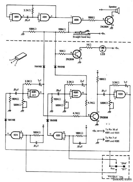
The circuit consists of a basic oscillator (above dashed line) and an automatic keyer (below dashed line). The unit can be used with a straight hand key or a paddle key for automatic operation. (View)
View full Circuit Diagram | Comments | Reading(622)
dc_OUTPUT_CHOPPER
Published:2009/6/23 1:49:00 Author:Jessie

Any dc voltage source in the 2- to 15-V range can be chopped into a unipolar square wave that has a peak amplitude nearly equal to the dc source voltage with circuit (lightly loaded CMOS will swing within a few millivolts of each rail at low frequencies). Depending on the actual voltage of the supply, the programmable-unij unction-transist or (PUT) relaxation oscillator produces 2000-Hz trigger pulses. These pulses operate the cascaded 74C107 flip-flop, producing a square wave. (View)
View full Circuit Diagram | Comments | Reading(1345)
Computer motherboard circuit diagram 810 1_32
Published:2011/7/27 20:59:00 Author:Ecco | Keyword: Computer motherboard
View full Circuit Diagram | Comments | Reading(558)
CRYSTAL_OSCILLATOR_I
Published:2009/6/23 1:49:00 Author:Jessie

In this circuit, series-resonant crystal XTAL1 is used as a frequency-determining element.XTAL1 is between 0.1 to 10 MHz. (View)
View full Circuit Diagram | Comments | Reading(1131)
| Pages:1377/2234 At 2013611362136313641365136613671368136913701371137213731374137513761377137813791380Under 20 |
Circuit Categories
power supply circuit
Amplifier Circuit
Basic Circuit
LED and Light Circuit
Sensor Circuit
Signal Processing
Electrical Equipment Circuit
Control Circuit
Remote Control Circuit
A/D-D/A Converter Circuit
Audio Circuit
Measuring and Test Circuit
Communication Circuit
Computer-Related Circuit
555 Circuit
Automotive Circuit
Repairing Circuit