
Circuit Diagram
Index 1367
ac_POWER_CONTROLLER
Published:2009/6/23 3:04:00 Author:May

This circuit is used to vary the power delivered to a 120-Vac load under software control. A 68705 micro controller can control eight discrete power triacs, each of which delivers power in 82 smoothly graduated steps, ranging from 0 to 97% of full power. The value delivered to one channel is independent of the value delivered to any other channel. Loads can include light displays, universal motors, heaters, and other appliances.The power level is set by software, not a potentiometer. The software includes a basic set of routines for processing interrupts and setting the power level. The software also includes five test and demonqtration routines for putting the circuit through its paces. Moreover, there's plenty of room to add your own routines to the 68705's built-in EPROM.The basic circuit is simple, yet versatile enough to accept inputs from on-board DIP switches; al-ternatively, the inputs can be driven from a microcomputer bus or parallel port, or a stand-alone device with TTL-compatible outputs. There are 12 input bits to set modes and specify values. (View)
View full Circuit Diagram | Comments | Reading(0)
WATER_ACTIVATED_ALARM
Published:2009/6/23 3:42:00 Author:Jessie

When sensor gets wet, it conducts, forward-biases Q1, and activates audio oscillator U1. A tone is heard from the speaker. (View)
View full Circuit Diagram | Comments | Reading(1811)
TRANSFORMERLESS_dc_POWER_SUPPLY_II
Published:2009/6/23 3:39:00 Author:Jessie

Although it is simple, this supply can provide 10 to 15 V at 100 mA directly from the ac lines. This circuit has no isolation from the ac line; therefore, there is a shock hazard and it should only be used where no possibility of contacting external devices, circuits, or personnel exists. (View)
View full Circuit Diagram | Comments | Reading(1110)
DIODELESS_PEAK_HOLD_CIRCUIT
Published:2009/6/23 3:38:00 Author:Jessie

The input pulse is fed into the sample-and-hold amplifier (an inexpensive AD582), as well as the comparator U3. The SHA's output also is fed into the comparator. If the input pulse is higher in am-plitude than the SHA's output, the comparator output goes low and the 4538 one-shot produces a l0-ps pulse that is fed back to cause the SHA to sample and then hold the voltage. Subsequent input voltages that are less than the held value won't cause the one-shot to fire again.Gates U4A and U4B are used to inhibit the sampling when necessary. Gates U4C and U4D, at the one-shot's output, can force the AD 582 into the sample mode. This feature is useful to reset the output to zero by forcing a sample when the input to the AD582 is zero. The polarity of the peak-hold circuit can be easily changed from positive-to-negative peak hold by reversing the inputs of the comparator. (View)
View full Circuit Diagram | Comments | Reading(2179)
ACID_RAIN_MONITOR
Published:2009/6/23 3:37:00 Author:Jessie

The drain-to-source resistance of Q1 varies depending on the acidity of the sample presented to Q1's gate circuit. That variable resistance varies the current flowing through the bridge; that current is proportional to pH. (View)
View full Circuit Diagram | Comments | Reading(1967)
FET_OP_AMP_MICROPHONE_MIXER
Published:2009/6/23 3:03:00 Author:May

View full Circuit Diagram | Comments | Reading(613)
_5_V_AT_15__TO_3_A_SIPPLY_6__TO__15_V_INPUT
Published:2009/6/23 3:37:00 Author:Jessie

Operating efficiencies of 80 to 90%are possible using the MAX741D and this circuit. (View)
View full Circuit Diagram | Comments | Reading(665)
BIRD_FEEDER_MONITOR
Published:2009/6/23 3:35:00 Author:Jessie

The first amplifier circuit is a bird phone. In this circuit, the electret mike (MIC1) is mounted in the neck of a large plastic funnel. The amplifier, built around an MC34119 (which is available from D.C. Electronics, P.O. Box 3203, Scottsdale, AZ 85271-3203; Tel. 800-467-7736, and elsewhere), is then placed outside of the funnel with the pick-up facing a nearby bird feeder. The output of the amplifier is then connected to a 16-Ω speaker.
The amplifier's voltage gain is determined by the values of the input resistor (R1) and the feed-back resistor (R3 and R4, respectively). The differential gain of the amplifier is given by: R3 + R4/R1 × 2. With the component values shown, the maximum voltage gain is about 270. This permits listening to the activity at the bird feeder. (View)
View full Circuit Diagram | Comments | Reading(2743)
Capacitor circuit diagram in capacitor dropping vlotage source
Published:2011/7/20 20:18:00 Author:Ecco | Keyword: Capacitor , capacitor, dropping vlotage, source

In the commonly low-voltage power supply, comparing with the transformer, the capacitor dropping vlotage source has the advantages of small size, economical, reliable, high efficiency, the disadvantage is that the safety is not as good as the power transformer. The AC is leaded to the load by the capacitor, then it has 220V voltage on the ground, which will cause electric shock easily, but if the circuit is used in the internal circuit power supply which has no human contact, this weakness can be overcome. For example, the refrigerator thermostat or remote control of electronic power supply, etc. are all open ╱ off by the capacitor dropping vlotage source.
(View)
View full Circuit Diagram | Comments | Reading(393)
DUAL_TONE_GENERATOR_FOR_AUDIO_SERVICING
Published:2009/6/23 3:34:00 Author:Jessie

This dual-tone generator can insert a distinctive tone in the audio section of a circuit under test.That way, you can work your way back from the speaker, stage-by-stage, to locate a faulty section. (View)
View full Circuit Diagram | Comments | Reading(0)
UNITY_GAIN_FOUR_INPUT_AUDIO_MIXER
Published:2009/6/23 3:02:00 Author:May

The circuit has four inputs. The voltage gain between each input and the output is held at unity by the relative values of the 470kΩ input resistor and the 470kΩ feedback resistor. (View)
View full Circuit Diagram | Comments | Reading(934)
PRECISION_AVSOLUTE_VALUR_CIRCUIT
Published:2009/6/23 3:02:00 Author:May

View full Circuit Diagram | Comments | Reading(535)
PIEZOELECTRIC_BUFFER
Published:2009/6/23 3:00:00 Author:May
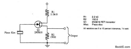
This circuit will serve as a buffer for experiments with Kynar film, a piezoelecffic material, or with piezo devices. (View)
View full Circuit Diagram | Comments | Reading(1706)
×10_OPERATIONAL_AMOLIFIER_USING_L161
Published:2009/6/23 3:00:00 Author:May
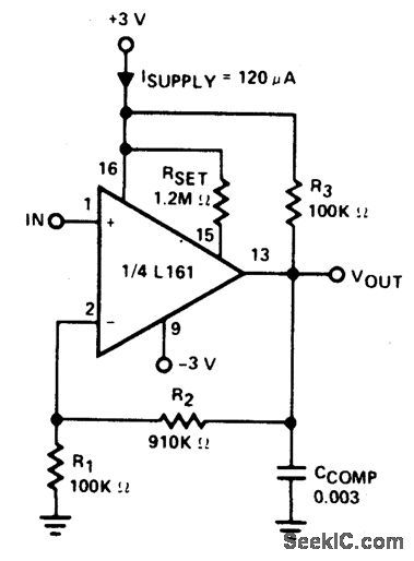
Amplifier is 3 dB down at 100 kHz and has a slew rate of 0.02V/μ sec. (View)
View full Circuit Diagram | Comments | Reading(473)
Switching elements on-off speed controller circuit diagram
Published:2011/7/20 20:19:00 Author:Ecco | Keyword: Switching elements , on-off , speed , controller

Pin 9 (VC) is used for the promotion of external switching devices. In order to avoid the effect on the pin from the pulse current effect, it should be connected a buffer capacitor between the pin and the ground (pin 11) to suppress interference caused by the current pulse. In addition, in order to adjust the external switching components on-off speed, it could be added a resistor between the buffer capacitor and pin, and the circuit is shown in Figure 9-36. From the figure, we can see, when power MOSFET gate is turned on, the resistance is Rg + R'g, and when it is turn-off, the gate resistance is only Rg.
(View)
View full Circuit Diagram | Comments | Reading(503)
CONTACT_DEBOUNCER
Published:2009/6/23 3:00:00 Author:May

A contact debouncer using a Schmitt trigger, such as a TTL7414, provides a clean pulse from a switch contact closing. (View)
View full Circuit Diagram | Comments | Reading(649)
PIEZOELECTRIC_DRIVER_CIRCUIT
Published:2009/6/23 2:59:00 Author:May

Three-terminal piezoelectric elements are typically driven by transistor circuits (A), or logic gates (B). Two-terminal devices can be driven by two NAND gates. A booster coil is used to compensate for the sound-pressure attenuation caused by the case. (View)
View full Circuit Diagram | Comments | Reading(1)
POSITIVE_FEEDBACK_CABLE_TERMINATOR
Published:2009/6/23 3:18:00 Author:Jessie

Positive feedback along with a series output resistor can provide a controlled output impedance from an op-amp circuit. The circuit is useful when driving coaxial cables that must be terminated at each end in their characteristic impedance, which is often 50Q. Adding a 50-Q series resistor on the op amp's output obviously reduces the available signal swing. (View)
View full Circuit Diagram | Comments | Reading(1037)
FET_MICROPHONE_MIXER
Published:2009/6/23 2:59:00 Author:May

A JFET transistor is used as a high-to-low impedance converter and signal mixen Input impedance is approximately 500 kΩ but it can be increased by increasing R5 to R8 as high as 10 MΩ. Output Z is about 2 kΩ, but it can be increased or decreased by changing the value of R10 Use 560 or 680 Ω to feed a 600-Ω input; use 100 kΩ to 1 MΩ for high irnpedance. (View)
View full Circuit Diagram | Comments | Reading(876)
×100_OPERATIONAL_AMLIFIER_USING_L161
Published:2009/6/23 2:59:00 Author:May
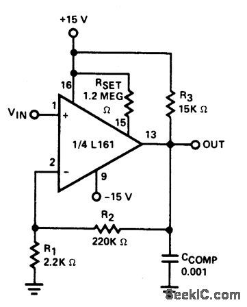
Amplifier has gain-bandwidth priduct of 20 MHz with slew rate of 0.3V/μ sec. (View)
View full Circuit Diagram | Comments | Reading(521)
| Pages:1367/2234 At 2013611362136313641365136613671368136913701371137213731374137513761377137813791380Under 20 |
Circuit Categories
power supply circuit
Amplifier Circuit
Basic Circuit
LED and Light Circuit
Sensor Circuit
Signal Processing
Electrical Equipment Circuit
Control Circuit
Remote Control Circuit
A/D-D/A Converter Circuit
Audio Circuit
Measuring and Test Circuit
Communication Circuit
Computer-Related Circuit
555 Circuit
Automotive Circuit
Repairing Circuit