
Circuit Diagram
Index 1379
SWR_WARNING_INDICATOR
Published:2009/6/23 1:47:00 Author:Jessie

Op amp with dc input from SWR metercan be adjusted to preset the SWR reading at which the LED lights. (View)
View full Circuit Diagram | Comments | Reading(0)
CODE_PRACTICE_OSCILLATOR_1
Published:2009/6/23 1:46:00 Author:Jessie

Oscillator, works with 2 to 12 Vdc (but 9 to 12 volts gives best volume and clean keying). R1 can be replaced with a 500 K pot and the circuit wili sweep the entire audio frequency range. (View)
View full Circuit Diagram | Comments | Reading(1456)
A SCR exchanging switch circuit diagram
Published:2011/7/28 2:53:00 Author:Ecco | Keyword: SCR , exchanging switch
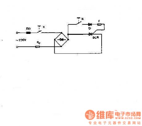
The SCR is the switch of electrical equipment,which is used to conduct and cut off the electric, andit has the advantages of no contact beating and arc, small mechanical noise and radio frequency interference, high switching speed and small size. It's suitable for dangerous places with flammable gas which could cause explosion easily. The circuit is shown as the chart: It is a simple SCR exchanging switch circuit. When switch K closes, SCR turns on, the value of R generally selects thousands of Ω.
(View)
View full Circuit Diagram | Comments | Reading(448)
REMOTE_RE_CURRENT_READOUT
Published:2009/6/23 1:45:00 Author:Jessie
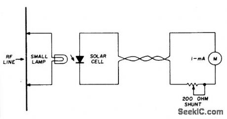
A suitable pilot lamp is illuminated by a small sample of rf and energizes an inexpensive solar cell; the dc current generated by the cell is a measure of relative rf power, and may be routed to a low-current meter located at any convenient point. A sensitive, low-current pilot lamp is desirable to cause minimum dis-turbance to normal rf circuit conditions. The number 48 or 49, 60 mA lamp is suitable for use with transmitters above 1-watt output. (View)
View full Circuit Diagram | Comments | Reading(1214)
MC33035 over-current protection circuit diagram
Published:2011/7/28 21:32:00 Author:Ecco | Keyword: over-current protection circuit

MC33035 overcurrent protection circuit is shown as the chart. MC33035 uses the external inverter to be grounded by resistor RS for the current sampling. Sampling voltage is input to the current sense comparator by pin 9 and pin 15. Inverting input of the comparator (pin 15) is set a 100mV reference voltage, which is used as the current limit ing benchmark. In the oscillator sawtooth rising time, if the current is too large, the comparator will flip so that the next RS flip-flop resets and closes the driven output to limit the current from continuing increase.
(View)
View full Circuit Diagram | Comments | Reading(1366)
Temperature controller circuit diagram 4
Published:2011/7/28 21:44:00 Author:Ecco | Keyword: Temperature controller

The temperature controller circuit is composed of the power supply circuit, temperature detection control circuit and control implementation circuit, and it is shown as the chart. Power supply circuit is composed of the power switch s, power transformer T, bridge rectifier UR, filter capacitors C1 ~ C3, three-terminal voltage regulator integrated circuit IC1, resistor R2 and power indicator LED VL1. Temperature detection control circuit is composed of the temperature detection diode VD1, resistors R3 ~ R1O, operational amplifier integrated circuit IC2 (N1 ~ N3) and the potentiometer RP. R1 ~ R12 select the 1/4W metal film resistors. RP uses a linear potentiometer. C1 selects the aluminum electrolytic capacitor with voltage in 25V.
(View)
View full Circuit Diagram | Comments | Reading(790)
SELF_POWERED_CW_MONITOR
Published:2009/6/23 1:44:00 Author:Jessie

Position L near the transmitter output tank to hear the key-down tone。Then tape the coil In place. C=.047μF,R=8.2 K,Q=HEP 253(or equal),T=500:500 ohm center tapped transformer. L = 2 to 6 turns on 1/2'' coil from. (View)
View full Circuit Diagram | Comments | Reading(0)
OUTPUT_TO_CURRENT_CONVERTER
Published:2009/6/23 1:44:00 Author:Jessie

Occasionally, it is preferable to generate a cur-rent, rather than a voltage, output into the load.The availability of differential inputs aJlows this to be accomplished in any of the four basic modes.If the output is to integrated, ZL can be sim-ple high-quality capacitor, unloaded by an op amp connected as a high-impedance follower.Note that, if desired, one side of a rest switch can be grounded.The compliance constraint for this configura-tion, where VL is an arbitrary common-mode po-tential, is: |VL+IOUT(ZL+RS)|≤12V (View)
View full Circuit Diagram | Comments | Reading(1270)
VARIABLE_FREQUENCY_ASTABLE_II
Published:2009/6/23 1:43:00 Author:Jessie

This circuit uses a single potentiometer and switched capacitors to cover 2 Hz to 30 kHz。 (View)
View full Circuit Diagram | Comments | Reading(1340)
KIA Maxima Sedan ABS Circuit
Published:2011/7/17 23:48:00 Author:Felicity | Keyword: KIA Maxima Sedan, ABS Circuit

View full Circuit Diagram | Comments | Reading(732)
ASTABLE_OSCILLATOR_II
Published:2009/6/23 1:43:00 Author:Jessie

By using transistor switch Q1/R2/R3, the frequency of an astable oscillator can be changed with a dc voltage or logic level. (View)
View full Circuit Diagram | Comments | Reading(1215)
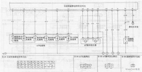
KIA Maxima Sedan Automatic Transmission Circuit (the 2nd)
Published:2011/7/17 23:52:00 Author:Felicity | Keyword: KIA Maxima Sedan, Automatic Transmission Circuit, (the 2nd)
View full Circuit Diagram | Comments | Reading(717)
AUTOMATIC_TAPE_RECORDING
Published:2009/6/23 1:42:00 Author:Jessie

Amateurs don’t haveto missthe action while away from the tug.This circuit turns on a tape recorder whenever the recelver’s squelch IS broken. After signal loss, the recorder will shut off following a slight delay. (View)
View full Circuit Diagram | Comments | Reading(1078)
CURRENT_TO_VOLTAGE_CONVERTER_FOR_GROUNDED_LOADS
Published:2009/6/23 1:42:00 Author:Jessie

This circuit uses an Analog Devices AD830 video difference amplifier. The circuit consists of two differential inputs. Unlike a conventional op amp, the AD830's output is nulled when the sum of the differences of the two inputs is zero.The AD830's stated unity-gain bandwidth is 60 MHz, and the device is capable of driving up to ±30 mA directly. The differential input voltage is limited to ±2V, while the maximum power supply is ±15 V.If more output current is desired, the AD830 can drive a bipolar transistor (such as an MJE200) directly. This will produce a one-sided output.A ferrite bead can be placed on the base to prevent oscillation under some conditions. Com-pensation can be added by splitting RS, and adding a variable capacitor. A resistor can be po-sitioned at the input to match the amplifier's in-put to a transmission line. (View)
View full Circuit Diagram | Comments | Reading(1456)
CODE_PRACTICE_OSCILLATOR
Published:2009/6/23 1:41:00 Author:Jessie

This simple cpo uses the 7404 low-power Schottky hex inverter. C is a 5- to 30-μF electrolytic selected for the desired pitch. The speaker is a 2-inch, 8-ohm unit. (View)
View full Circuit Diagram | Comments | Reading(452)
ASTABLE_OSCILLATORI
Published:2009/6/23 1:41:00 Author:Jessie


In this circuit,two gates from the quad 4093 package are used to form a simple astable squarewave oscillator.The values for RX and CX are approximately as follows∶These values can be scaled for other frequencies. (View)
View full Circuit Diagram | Comments | Reading(2562)
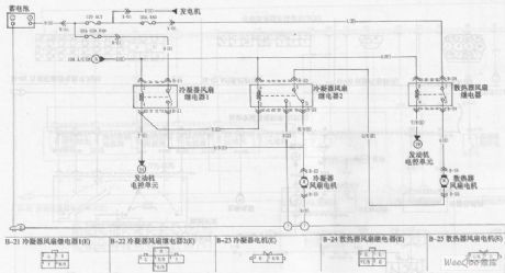
KIA Maxima Car Cooling System Circuit
Published:2011/7/18 0:01:00 Author:Felicity | Keyword: KIA Maxima, Car Cooling System, Circuit
View full Circuit Diagram | Comments | Reading(808)
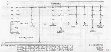
KIA Maxima Car Engine Circuit (the 4th)
Published:2011/7/17 23:59:00 Author:Felicity | Keyword: KIA Maxima Car Engine Circuit (the 4th)
View full Circuit Diagram | Comments | Reading(668)
PREAMP_TRANSMIT_RECEIVE_SEQUENCER
Published:2009/6/23 1:41:00 Author:Jessie
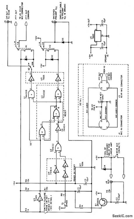
This circuit is useful in amateur radio VHF and UHF work where a mast-mounted antenna preamp is used for receiving. The kit controls T-R switching and change-over relay sequencing so that high RE levels are prevented from accidentally being applied to the preamplifier during switching intervals. (View)
View full Circuit Diagram | Comments | Reading(1435)
KIA Maxima Car Engine Circuit (the 3rd)
Published:2011/7/17 23:58:00 Author:Felicity | Keyword: KIA Maxima, Car Engine Circuit, (the 3rd)

View full Circuit Diagram | Comments | Reading(712)
| Pages:1379/2234 At 2013611362136313641365136613671368136913701371137213731374137513761377137813791380Under 20 |
Circuit Categories
power supply circuit
Amplifier Circuit
Basic Circuit
LED and Light Circuit
Sensor Circuit
Signal Processing
Electrical Equipment Circuit
Control Circuit
Remote Control Circuit
A/D-D/A Converter Circuit
Audio Circuit
Measuring and Test Circuit
Communication Circuit
Computer-Related Circuit
555 Circuit
Automotive Circuit
Repairing Circuit