
Circuit Diagram
Index 1381
Beijing Pajero SUV Engine Control System (A / T) Circuit (the 2nd)
Published:2011/7/18 0:14:00 Author:Felicity | Keyword: Beijing Pajero SUV, Engine Control System (A / T), Circuit, the 2nd)

View full Circuit Diagram | Comments | Reading(730)
LOW_FREQUENCY_ASTABLE
Published:2009/6/22 23:49:00 Author:May


By using a high-gain low-current transistor, such as the 2N3565, a pair of Darlington-connected transistors (2N3565 and 2N3904) can be used in a high-impedance configuration. (View)
View full Circuit Diagram | Comments | Reading(0)
Simple Series Adjustable Regulator Circuit
Published:2011/7/18 5:26:00 Author:Felicity | Keyword: Simple Series Adjustable, Regulator Circuit

View full Circuit Diagram | Comments | Reading(626)
BOAT_ALARM
Published:2009/6/22 23:48:00 Author:May

Removing R1 or R2 from the circuit (i.e., the potentiai thief breaks a hidden wire that connects R1 to +12 V and R2 to ground) activates the alarm for about five minutes. (View)
View full Circuit Diagram | Comments | Reading(724)
Hyundai Sonata Car Cruise Control Circuit (the 2nd)
Published:2011/7/18 3:15:00 Author:Felicity | Keyword: Hyundai Sonata Car, Cruise Control, Circuit, (the 2nd)

View full Circuit Diagram | Comments | Reading(992)
Multi-frequency signal generator
Published:2011/7/28 3:22:00 Author:Ecco | Keyword: Multi-frequency , signal generator
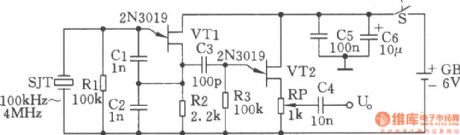
The chart shows the multi-frequency signal generator. SJT and VTl form a crystal oscillator. SJT is used as a quartz crystal equivalent inductance, the equivalent Q value is high, the other components and stray parameters have minimal effect on the oscillation frequency, so the frequency stability is high. VT2, etc. constitute a source follower to get low output impedance and an dampening effect to avoid the load to affect the crystal stability. In order to obtain more frequency signs to calibrate the receiver, it can use a square wave circuit shown as below. This circuit can instead of the the C3 in above figure, and be connected between the source of VT1 and grid of VT2, then it will generate rich harmonic signals (such as the l00kHz crystal can produce 30MHz harmonic signals). It can be used as frequency sign for calibrating general high frequency receiver.
(View)
View full Circuit Diagram | Comments | Reading(547)
MOTION_ACTIVATED_MOTORCYCLE_OR_CAR_ALARM
Published:2009/6/22 23:47:00 Author:May
Trembler (motion activated) switch sounds the alarm for 5 seconds. Then it goes off. Circuit is timed out for 10 seconds to allow the trembler switch to settle. (View)
View full Circuit Diagram | Comments | Reading(1234)
225_W_15_V_OUTPUT_CONVERTER_20_kHz_inverter
Published:2009/6/22 23:47:00 Author:May

A converter designed to supply t15 Vdc is shown. This converter is several times lighter in weight than an equivalent.
C1 -2500 μF,350 V Electrolyic Q1,Q5,Q6,-2N6307C2—0.1μF Disc Ceramic Q2,Q4 - 2N5052C3—0.1μF Paper Q3—2N5345C4—10 μF Electrolylc Q7-2N4870C5—0.25μF Paper Q8 -2N3905D1—MDA-980-4 Bridge Rectifier Assembly Q9—2N3903 D2,D3,D4,D5-1N5826,20V 15A
All Resistors in Ohms and 1/2 W Unless Otherwise Noted
R1—1,10 W R10-1KR2-100 R11-10KR3-82R12-270R4- 22K R13-1KR5-1.5K,15W R14-7.5KR6-200 R15-2.5KR7-15 R16-5KR8—4.7K 17-3.5KP9-51
T1 - Core -Magnetics Inc 80623-1/2 D-080N1,N2-20 Turns Each,No 30 AWG(Bifilar)N3,N4- 3 Turns Each,No 20 AWG
T2—Core—Arnold 6T 5800 D1N1,N2-100 Turns Each,No. 20 AWG(Bifilar)N3-7 Turns No. 20 AWGN4-12 Turns Each No 12 AWG(No 16 AWG,3 In Parallel)
Z1 —1N4733,5.1 VZ2,Z3 -1N4760,68VZ4- 1N4736 (View)
View full Circuit Diagram | Comments | Reading(894)
LATCHING_BURGLAR_ALARM
Published:2009/6/22 23:46:00 Author:May

When the protective circuit is interrupted (opened), the alarm sounds. To set the circuit, adjust R2 (with protective circuit open) for 1 V across R1. (View)
View full Circuit Diagram | Comments | Reading(965)
LOW_DISTORTION_SINE_WAVE_OSCILLATOR
Published:2009/6/22 23:46:00 Author:May

C1,C2Min.Frequency Max.Frequency0.47μF 18 Hz 80 Hz 0.1μF 80 Hz 380 Hz 0.022μF 380 Hz 1.7 kHz0.0047μF 1.7 kHz 8 kHz0.002μF 4.4 kHz 20 kHz (View)
View full Circuit Diagram | Comments | Reading(0)
TAMPER_PROOF_BURGLAR_ALARM
Published:2009/6/22 23:45:00 Author:May
If R2 is opened or shorted, the alarm sounds. (View)
View full Circuit Diagram | Comments | Reading(542)
Hyundai Sonata Car Airbag System Circuit (the 3rd)
Published:2011/7/18 3:20:00 Author:Felicity | Keyword: Hyundai Sonata Car, Airbag System, Circuit, (the 3rd)
View full Circuit Diagram | Comments | Reading(1043)
TONE_BURST_GENERATOR
Published:2009/6/22 23:45:00 Author:May

The burst length IS digitally controlled by inputs A,B,C,D.This input selects the necessary values ofR and C,The circuit shown in the figure generates a burst oftone followed by a silent period,then another tone burst is sounded and so forth,The timing of the tone bursts is digitally controlledvia the CD4066(IC2). A parts list for this circuit is given in the table.
IC1 556 dual timer(or two 555 timers)C5 0.047-μF capacitorIC2 CD4066 quad bilateral switchR1 100-kΩ, 1/4-W 5% resistorC1 1-μF,25-V electrolytic capacitorR2,R4 220-kΩ, 1/4-W 5% resistorC2 4.7-μF, 25-V electrolytic capacitor R3 680-kΩ, 1/4-W 5% resistorC3 10-μF, 25-V electrolytic capacitor R5 12-kΩ, 1/4-W 5% resistorC4,C60.01-μF capacitor R6 4.7-kΩ, 1/4-W 5% resistor (View)
View full Circuit Diagram | Comments | Reading(0)
AUTO_BURGLAR_ALARM
Published:2009/6/22 23:44:00 Author:May

Dome light current through L1 closes reed switch and sounds alarm. Shaker switch also activates alarm. (View)
View full Circuit Diagram | Comments | Reading(1000)
Hyundai Sonata Car Airbag System Circuit (the 2nd)
Published:2011/7/18 3:19:00 Author:Felicity | Keyword: Hyundai Sonata Car, Airbag System, Circuit, (the 2nd)
View full Circuit Diagram | Comments | Reading(834)
ANTITHEFT_DEVICE
Published:2009/6/22 23:43:00 Author:May
Any momentary break In the protective loop or tripping of the normally closed vibration sensor,causes alarm to sound for 20 seconds,If the circuit is open all the time,the alarm will sound continuously. (View)
View full Circuit Diagram | Comments | Reading(644)
Hyundai Sonata Car Airbag System Circuit (the 1st)
Published:2011/7/18 3:17:00 Author:Felicity | Keyword: Hyundai Sonata Car, Airbag System, Circuit, (the 1st)

View full Circuit Diagram | Comments | Reading(1436)
Hyundai Sonata Car Blower And Air Conditioning Control System (Automatic) Circuit (the 4th)
Published:2011/7/18 4:46:00 Author:Felicity | Keyword: Hyundai Sonata Car, Blower And Air Conditioning, Control System, (Automatic), Circuit, (the 4th)
View full Circuit Diagram | Comments | Reading(1267)
BASIC_LM3909_AUDIO_OSCILLATOR
Published:2009/6/22 23:42:00 Author:May

The LM3909's oscillator frequency can be fine-tuned by adding a resistor to a basic circuit. (View)
View full Circuit Diagram | Comments | Reading(761)
ONE_TRANSISTOR_PHASE_SHIFT_OSCILLATOR
Published:2009/6/22 23:41:00 Author:May

A single transistor is used as an active element in an RC phase shift oscillator. (View)
View full Circuit Diagram | Comments | Reading(2516)
| Pages:1381/2234 At 2013811382138313841385138613871388138913901391139213931394139513961397139813991400Under 20 |
Circuit Categories
power supply circuit
Amplifier Circuit
Basic Circuit
LED and Light Circuit
Sensor Circuit
Signal Processing
Electrical Equipment Circuit
Control Circuit
Remote Control Circuit
A/D-D/A Converter Circuit
Audio Circuit
Measuring and Test Circuit
Communication Circuit
Computer-Related Circuit
555 Circuit
Automotive Circuit
Repairing Circuit