
Circuit Diagram
Index 1386
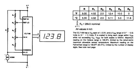
BASIC_DIGITAL_THERMOMETER
Published:2009/6/22 23:05:00 Author:May
View full Circuit Diagram | Comments | Reading(0)
The light sensor application circuit
Published:2011/7/21 2:21:00 Author:Seven | Keyword: light sensor, application circuit

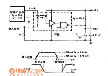
figure 4-7 the pulse minitor(probe) circuit (View)
View full Circuit Diagram | Comments | Reading(824)
AUDIBLE_CONTINUITY_TESTER
Published:2009/6/22 23:35:00 Author:Jessie

View full Circuit Diagram | Comments | Reading(1370)
FREQUENCY_DOUBLER
Published:2009/6/22 23:05:00 Author:May

An Analog Devices AD734 four-quadrant analog multiplier is used as a frequency doublen. (View)
View full Circuit Diagram | Comments | Reading(0)
The photodiode application circuit
Published:2011/7/21 2:37:00 Author:Seven | Keyword: photodiode, application circuit

View full Circuit Diagram | Comments | Reading(1548)
The analog light isolator application circuit
Published:2011/7/21 2:38:00 Author:Seven | Keyword: analog, light isolator, application circuit
View full Circuit Diagram | Comments | Reading(865)
HOOK_SENSOR_ON_4__TO_20_mA_LOOP
Published:2009/6/22 23:05:00 Author:May

Here's an effective for a temperature sensor to receive power from a 4-to-20 mA loop without actually affecting the loop current (see the figure). This particular temperature sensor IC (AD590F) conducts 1 μA/K when powered by a supply in the range of 4 V to 40 Vdc.The scheme uses a 5-V Zener diode (D1) to regulate the power source for AD590F. Most of the current flows through the Zener diode and a small current flows through AD590F. A high-impedance device can read the temperature information across R1, which is a 1 mV/K in the range of -55℃ to 150℃. The waste of power is negligible in this arrangement. (View)
View full Circuit Diagram | Comments | Reading(1007)
The loudspeaker power amplitude limiter circuit
Published:2011/7/24 7:35:00 Author:Seven | Keyword: power amplitude limiter
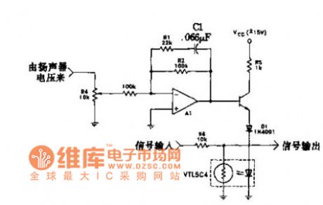
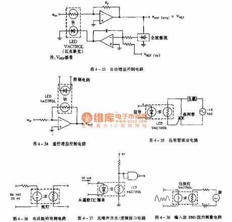
In the figure is the circuit which utilizes the amplitude limiter to reduce the low frequency power. Under 200HZ, the circuit limits the threshold voltage. When it is low frequency, the amplifier A1 gain is 1. The amplifier is starting when it is 25HZ, the gain is 6Db/octave, and it is cut off, R4 is used to adjust the impedance. VBE of Q1, voltage drop of D1, voltage of LED, they together set the threshold voltage which is 2.8V or so(peak) or 2.0V(RMS). A01 is used to weaken the signal voltage.
(View)
View full Circuit Diagram | Comments | Reading(804)
SIMPLE_EVENT_COUNTER
Published:2009/6/22 23:03:00 Author:May

S1 is a power switch. U2 drives counter U3 by producing a pulse when S2 is depressed. U4 and DISP1 read the count of counter IC U3. S3 is a reset to zero switch. The counter is a basic one-digit circuit useful as a holding block or by itself. (View)
View full Circuit Diagram | Comments | Reading(3777)
The photocoupler-optoisolator circuit
Published:2011/7/21 2:17:00 Author:Seven | Keyword: photocoupler-optoisolator
View full Circuit Diagram | Comments | Reading(785)
7805_TURN_ON_CIRCUIT
Published:2009/6/22 23:03:00 Author:May

A logic level can control a 7805 regulator with this circuit. Q2 is a series switching transistor controlled by Q1. Q1 is tumed on by a logic voltage to its base. (View)
View full Circuit Diagram | Comments | Reading(2479)
The electric programmable gain amplifier circuit
Published:2011/7/21 2:26:00 Author:Seven | Keyword: programmable gain amplifier

In the figure is the electric programmable gain amplifier circuit which is used in amplifiers. AOI has a LDR whose central head is connected with the ground, one side of it is connected with the signal channel, while the other with the control circuit. The signal amplifier consists of the op-amp A1, resistor R3, gain adjust resistor R2 and input resistor R5, the amplifier gain is shown in the figure.
(View)
View full Circuit Diagram | Comments | Reading(1170)
MICROPROCESSOR_SUPERVISORY_CIRCUIT
Published:2009/6/22 23:03:00 Author:May

This circuit provides a reset pulse during power up, down, or low-voltage battery back up, switching, a watchdog timer and a 1.25-V threshold detector for power failure or power fail warning, or to monitor another supply. (View)
View full Circuit Diagram | Comments | Reading(0)
KEY_WIRELESS_RTS_WITH_DATA
Published:2009/6/22 23:02:00 Author:May

This simple keyer supplies both the RTS control and data delay needed to interface a digital ra-dio with an RS-232, data-only system. It supports speeds to 19.2 kbits/s sync or async. (View)
View full Circuit Diagram | Comments | Reading(0)
COMPUTALARM
Published:2009/6/22 23:25:00 Author:Jessie

The circuit has a built-in, self-arming feature. The driver turns off the ignition, presses the arm button on the Computalarm, and leaves the car. Within 20 seconds, the alarm arms itself-all automatically! The circuit will then detect the opening of any monitored door, the trunk lid, or the hood on the car. Once acti-vated, the circuit remains dormant for 10 sec-onds. When the 10-second time delay has run out, the circuit will close the car's horn relay and sound the ham in periodic blasts (approxi-mately 1 to 2 seconds apart) for a period of one minute. Then the Computalarm automatically shuts itself off (to save your battery) and re-arms. If a door, the trunk lid, or the hood re-mains ajar, the alarm circuit retriggers and another period of horn blasts occurs. The Com-putalarm has a key switch by which the driver can disarm the alarm circuit within a 10-second period after he enters the door. The key switch consists of a closed circuit jack, J1, and a mating miniature plug. (View)
View full Circuit Diagram | Comments | Reading(1286)
THERMOMETER_FOR_5_V_OPERATION
Published:2009/6/22 23:02:00 Author:May

At the heart of this simple circuit is the well-known type KTY10 temperature sensor from Siemens. This silicon sensor is essentially a temp erature -dependent resistor that is connected as one arm in a bridge circuit here. Preset P1 functions to balance the bridge at 0℃. At that temperature, moving coil meter M1 should not deflect, i.e., the needle is in the center position. Temperature vari-ations cause the bridge to be unbalanced, and hence produce a proportional indication on the meter. Calibration at, say, 20℃ is carried out with the aid of P2.The bridge is fed from a stabilized 5.1-V supply, based on a temperature-compensated zener-diode. It is also possible to feed the thermometer from a 9-V battery, provided D1-D3, R1 and C1 are replaced with a Type 78L05 voltage regulator, because this is more economic as regards to current c onsumption. (View)
View full Circuit Diagram | Comments | Reading(0)
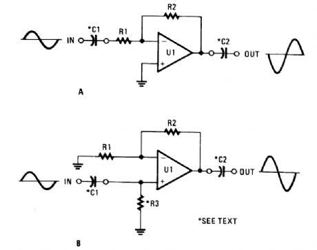
OP_AMP_OFFSET_NULL
Published:2009/6/22 23:24:00 Author:Jessie

Offset problems can occur in the best of circuits (and often do) without regard to whether the circuit is inverting (A), or noninverting (B). Offset-nulling potentiometers are useful in correcting the output to zero, but their effectiveness will vary under different conditions. (View)
View full Circuit Diagram | Comments | Reading(914)
OP_AMPS_WITH_LONG_RC_TIME_CONSTANTS
Published:2009/6/22 23:22:00 Author:Jessie
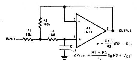


This circuit multiplies RC time constant to 1000 seconds and provides low output impedance.Cost is lowered because of reduced resistor and capacitor values. (View)
View full Circuit Diagram | Comments | Reading(660)
VIDEO,POWER,AND_CHANNEL_SELECT_SIGNAL_CARRIER
Published:2009/6/22 23:01:00 Author:May

In the video system of Figs. A and B, a single coaxial cable carries power to the remote location, selects one of eight video channels, and returns the selected signal. The system can choose one of several remote surveillance-camera signals, for example, and display the picture on a monitor near the interface box.
The heart of the multiplexer box (A) is a combination 8-channel rnultiplexer and amplifier (ICl). C11 couples the multiplexer's baseband video output to the coax, and L1 decouples the video from dc power arriving on the same line. This power-approximately 30 mA at 10 V-supplies all circuitry in the multiplexer box.
In interface box (B), a desired channel is encoded by three bits, set either by switches as shown or by an applied digital input. Momentary depression of the send button triggers clownconverter IC1 and gated oscillator IC2A to initiate a channel-selection burst. (View)
View full Circuit Diagram | Comments | Reading(0)
BASIC_OP_AMP_CIRCUITS
Published:2009/6/22 23:21:00 Author:Jessie
The two simplest op-amp configurations are the inverting (A) and the noninverting (B). Resistor R3 is needed only if C1 is used in the noninverting circuit. (View)
View full Circuit Diagram | Comments | Reading(803)
| Pages:1386/2234 At 2013811382138313841385138613871388138913901391139213931394139513961397139813991400Under 20 |
Circuit Categories
power supply circuit
Amplifier Circuit
Basic Circuit
LED and Light Circuit
Sensor Circuit
Signal Processing
Electrical Equipment Circuit
Control Circuit
Remote Control Circuit
A/D-D/A Converter Circuit
Audio Circuit
Measuring and Test Circuit
Communication Circuit
Computer-Related Circuit
555 Circuit
Automotive Circuit
Repairing Circuit