
Circuit Diagram
Index 1392
WHEATSTONE_BRIDGE
Published:2009/6/22 22:35:00 Author:May


This circuit can be used to measure resistances. R7 is calibrated and fitted with an indicator dial, Lhen:
A frequency of 1 kHz for the audio oscillator is usually used. (View)
View full Circuit Diagram | Comments | Reading(919)
50_MHz_FREQUENCY_COUNTER
Published:2009/6/22 22:34:00 Author:May
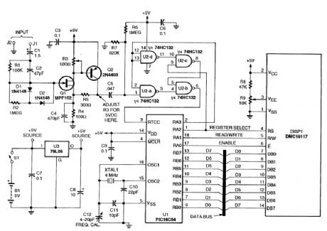
This inexpensive frequency counter uses a microcontroller as the counter. The rrticrocontroller feeds an LCD display module that accepts standard ASCII code. The frequency is displayed as Hz, kHz, or MHz and the counter is autoranging. (View)
View full Circuit Diagram | Comments | Reading(2586)
PULSED_DOUBLE_HETEROSTRUCTURE_LASER_DRIVER
Published:2009/6/22 22:34:00 Author:May

View full Circuit Diagram | Comments | Reading(701)
IC_LASER_DIODE_DRIVER
Published:2009/6/22 22:33:00 Author:May

View full Circuit Diagram | Comments | Reading(1226)
SINGLE_SUPPLY_BRIDGE_AMPLIFIER
Published:2009/6/22 22:33:00 Author:May
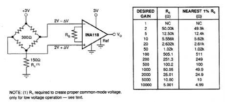
The INA118 can be used on single-power supplies of +2.7 to +36V. The figure shown is a basic single-supply circuit. The output Ref terminal is connected to ground. Zero differential input voltage will dentand an output voltage of 0V (ground). Actual output voltage swing is limited to approxi-mately 35 mV above ground, when the load is referred to ground as shown. The typical performance curve “Output Voltage”, Output Current shows how the output voltage swing varies with output current.
With single-supply operation, +VIN and -VIN must both be 1.1V above ground for linear operation. You cannot, for instance, connect the inverting input to ground and measure a voltage connected to the noninverting input.To illustrate the issues affecting low-voltage operation, consider the circuit in the figure. It shows the INA118, operating from a single 3-V supply. A resistor in series with the low side of the bridge en-sures that the bridge output voltage is within the common-rqode range of the amplifier's inputs. (View)
View full Circuit Diagram | Comments | Reading(1500)
LASER_dc_SUPPLY
Published:2009/6/22 22:33:00 Author:May

The supply provides about 6 kVdc when open circuited, dropping to around 1375 Vdc when loaded. The R099 is a laser tube. (View)
View full Circuit Diagram | Comments | Reading(715)
OP_AMP_DIODE_LASER_DRIVER
Published:2009/6/22 22:31:00 Author:May
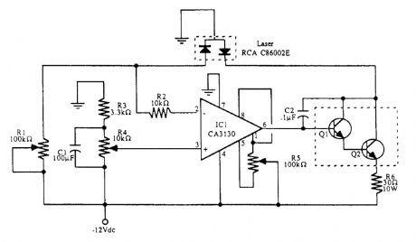
This circuit is one way to automatically adjust drive current using a discrete op amp. Use the transistors specified or replace them with a suitable Darlington power transistor (such as TIP 120).IC1RCA CA 313 operational amplifierR1,R5 100-kΩ potentiometerR2 10-kΩ resistorR3 3.3-kΩ potentiometerR4 10-kΩ potentiometerR6 30-Ω, 10-W resistorC1100-μF electrolytic capacitorC2 0.1-μF disc capacitorQ1 2N2101 transistorQ2 2N3585 transistorLaser RCA C86002 (or equivalent laser diode) (View)
View full Circuit Diagram | Comments | Reading(2151)
BATTERY_CONDITION_INDICATOR_FOR_12_V_BATTERIES
Published:2009/6/22 22:30:00 Author:May
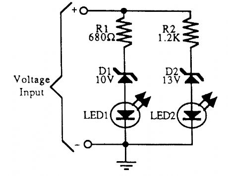
A simple battery condition indicator. Choose the Zener diodes to provide a window for over/un-der voltage indication. (View)
View full Circuit Diagram | Comments | Reading(1773)
LITHIUM_MEMORY_BACKUP_BATTERY_REPLACEMENT
Published:2009/6/22 22:30:00 Author:May

Physically very small high-capacitance capacitors are available for memory backup. Here, a 0.1-F (100,000μF) capacitor and two diodes replace the lithium battery. The lithium battery can be re-tained as well, providing double backup. (View)
View full Circuit Diagram | Comments | Reading(1164)
PLL_IR_LASER_LIGHT_RECEIVER
Published:2009/6/22 22:29:00 Author:May

Circuit schematics for the 555-based PLL laser light PFM receiver. Although R4 is shown as a resistor, you might want to sub-stitute it with a 10-kΩ precision potentiometer so that you can dial in the center frequency of the transmitter. Experiment with the value of C1 for the best high-frequency response. Notice that circuit is functionally identical to the laser light detector/receiver shown in the figure, but with the addition of the 565. (View)
View full Circuit Diagram | Comments | Reading(3233)
SPEAKERPHONE_ADAPTER
Published:2009/6/22 22:29:00 Author:May


Using a Motorola MC34118 speakerphone IC, this adapter can be used with a regular telephone to provide speaker capability. This device is powered from the phone Iine, but it can be powered via an extemal power supply if the line loop current is marginally low. An external phone is needed for ringing and dialing functions. (View)
View full Circuit Diagram | Comments | Reading(4157)
BATTERY_STATUS_INDICATOR
Published:2009/6/22 22:29:00 Author:May

In battery-powered circuitry, there are some advantages to having an indicator to show when the battery voltage is high enough for proper circuit operation. This is especially true for instruments that can produce erroneous data.The battery status indicator is designed for a 9-V source. It begins dimming noticeably below7V artd it extinguishes at 6 V. If the warning of incipient battery failure is not desired, R3 can be re-rnoved and the value ofJR, is halved. (View)
View full Circuit Diagram | Comments | Reading(3)
IR_LASER_LIGHT_DETECTOR
Published:2009/6/22 22:28:00 Author:May
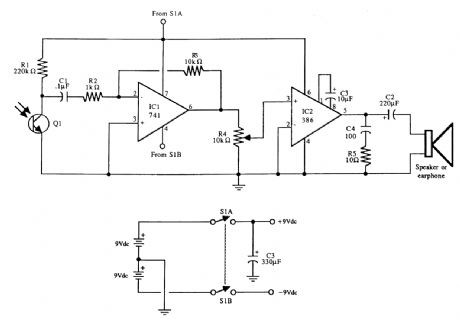
The universal Iaser light detector. The output of the LM386 audio amplifier can be connected to a small 8-Ω speaker or ear-phone. Two 9-V batteries provide power. Decrease R1 to lower sensitivity; increase R3 to increase gain of the op amp (avoid very high gain or the op amp might oscillate). Q1 is an infrared phototransistor. (View)
View full Circuit Diagram | Comments | Reading(2174)
BATTERY_CHARGE_INDICATOR
Published:2009/6/22 22:28:00 Author:May


When a battery is charging, a voltage drop across RSENSE causes Q1 to conduct,and lights LED1. RSENSE should be chosen as follows:
(View)
View full Circuit Diagram | Comments | Reading(1242)
MUSIC_ON_HOLD_BOX
Published:2009/6/22 22:28:00 Author:May

U1, an LS3404 melody chip is activated when hold S1 is pressed, which causes SCRI to con-cluct and hold the telephone line via T1, R1, and LED1. The voltage across R1 and LED1 is used to activate the melody chip. Q1 and Q2 form a restart circuit to keep the melody chip going during hold. (View)
View full Circuit Diagram | Comments | Reading(1424)
MOTORCYCLE_TUNE_UP_AID
Published:2009/6/22 22:28:00 Author:May
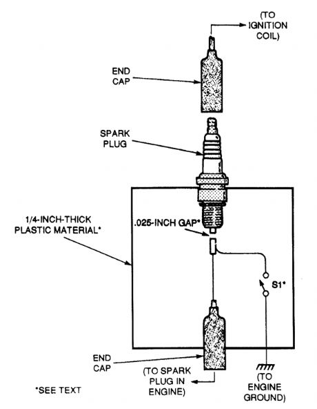
Performing a tune-up on a newer bike is made a lot easier with this helpful circuit. Because of the high voltages present, make sure that S1 has an insulated handle and that the fixture is grounded. With the ignition turned off, remove one of the spark plug wires and connect it to the spark plug on the fixture. Slip the fixture's end cap over the spark plug on the cycle and you're ready to go. Open S1 and start the engine. Then, close S1; the cylinder with the fixture should not fire and a spark should be seen at the fixed gap. Be sure that the fixture is cqnnected to the engine ground before closing S1 . (View)
View full Circuit Diagram | Comments | Reading(520)
LASER_DIODE_TRANSMITTER
Published:2009/6/22 22:27:00 Author:May

View full Circuit Diagram | Comments | Reading(1017)
LIGHT_BEAM_RECEIVER_AND_SOUND_EFFECTS_GENERATOR_FOR_LASER_PISTOLS
Published:2009/6/22 22:27:00 Author:May

Schematic diagram for light, beam amplifier and sound-effects generator (using a 555 timer IC and speaker). The light striking Q1 generates a siren-like sound. (View)
View full Circuit Diagram | Comments | Reading(911)
PHONE_LINE_INTERFACE
Published:2009/6/22 22:26:00 Author:May

This circuit should be useful for interfacing phone projects to the telephone line. It has a ringer, can interrupt the wiring, and isolates project from the phone line. (View)
View full Circuit Diagram | Comments | Reading(1735)
LOW_BATTERY_CIRCUIT
Published:2009/6/22 22:25:00 Author:May

A Maxim MAX691A series IC allows low-battery detection. (View)
View full Circuit Diagram | Comments | Reading(894)
| Pages:1392/2234 At 2013811382138313841385138613871388138913901391139213931394139513961397139813991400Under 20 |
Circuit Categories
power supply circuit
Amplifier Circuit
Basic Circuit
LED and Light Circuit
Sensor Circuit
Signal Processing
Electrical Equipment Circuit
Control Circuit
Remote Control Circuit
A/D-D/A Converter Circuit
Audio Circuit
Measuring and Test Circuit
Communication Circuit
Computer-Related Circuit
555 Circuit
Automotive Circuit
Repairing Circuit