
Circuit Diagram
Index 1397
PROGRAMMABLE_GAIN_INSTRUMENTATION_AMPLIFIER
Published:2009/6/19 4:29:00 Author:May

This is a two-op-amp programmable-gain instrumentation amplifier for single-supply applications. U1A and U1B are Analog Devices AD822 or OP-213 ICs. (View)
View full Circuit Diagram | Comments | Reading(561)
VARIABLE_GAIN_DIFFERENTIAL_INPUT_INSTRUMENTATION_AMPLIFIER
Published:2009/6/19 4:28:00 Author:May
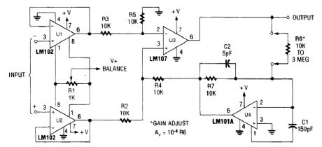
View full Circuit Diagram | Comments | Reading(950)
Nokia 6110 (5110) digital mobile phones relevant parts circuit diagram
Published:2011/5/6 1:33:00 Author:Jessie | Keyword: digital mobile phones

View full Circuit Diagram | Comments | Reading(678)
Simple hypnosis working principle circuit
Published:2011/5/6 1:31:00 Author:Jessie | Keyword: hypnosis
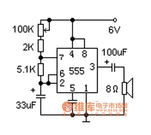
In this circuit, the time base circuit 555 conposes a very low frequency oscillator, and it outputs short pulses, which makes the speaker send out sound similar with raindrops. The speaker uses2 inches, 8 ohms small moving coil type. Raindrops soundspeed can be adjust to suitable degree by 100K potentiometer. Ifwe add a timing switch at power, so that can cut power in time when user asleep. (View)
View full Circuit Diagram | Comments | Reading(526)
Heat release infrared sensor induction control circuit 2
Published:2011/5/6 1:25:00 Author:Jessie | Keyword: Heat release infrared sensor, induction control
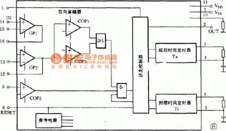
Photoconductive resistance R2 is used to detect environmental brightness, when the environment is bright, photoconductive resistance's value is smaller, it makes the pin 9 on low level, the output terminal 2 of pin IC1 is stable low level, switch tube deadline. If it needs to control circuit also can be used when environment is light, it just needs toremove R2. IC's pin 1 is thetriggered choice terminal, whenpin 1connects to high level, circuit works on repeatable; when pin 1 connects to grounding, circuit works on locking triggered. (View)
View full Circuit Diagram | Comments | Reading(435)
Pyroelectric infrared language alarm device principle circuit
Published:2011/5/6 1:19:00 Author:Jessie | Keyword: Pyroelectric infrared, language alarm device
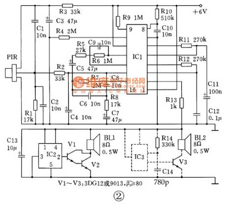
Pyroelectric infrared language alarm device circuit is shown in figure 2. Circuit is composed by pyroelectric infrared sensor, signal processing circuit and language alarm circuit. When people enter exclusionary area, pyroelectric infrared sensor (PIR) namely receive frequency 0 1 ~ 8Hz's infrared signal of the human body, and converts it into electrical signal, the resistance, capacitance C2 and C4 compose thelow pass filter circuits, filter high frequency interference noise, send to pin 14 of IC1, the signal is amplifered by internal level 2, after identified by two-way range in IC1, through the logic control circuit output high level from pin 2 of IC1, its time determined by R12, C12 in the circuit.
(View)
View full Circuit Diagram | Comments | Reading(578)
Vibration alarm circuit diagram
Published:2011/5/6 1:17:00 Author:Jessie | Keyword: Vibration alarm

Using an integrated circuitIC7556, two piezoelectric ceramic clamps X1 and X2, and several passive electronic components to compose a mechanical vibration alarm, which can produce a minute of alarm sound. As long as exert mechanical vibration on piezoelectric ceramics piece X1, it will produce avoltage on IC1a's pin 610MΩ resistance. When triggered, 7556 makes piezoelectric ceramics piece X2 alarm sound. The second time basecircuit IC1b produces self-excited signal which is adjusted by 5Hz low-frequency.
(View)
View full Circuit Diagram | Comments | Reading(1067)
4_TO_20_mA_PROCESS_CONTROLLER
Published:2009/6/19 4:27:00 Author:May

The figure shows how to use an LTC1453 to make an optoisolated digitally controlled 4-to 20-mA process controller. The controller circuitry, including the optoisolator, is powered by the loop voltage that can have a wide range of 3.3V to 30V. The 1.22-V reference output of the LTC1453 is used for the 4-mA offset current and VOUT is used for the digitally controlled 0-to 16-mA current. RS, is a sense resistor and the LT1077 op amp modulates the transistor Q1 to provide the 4-to 20-mA current through this resistor. The control circuitry consumes well under the 4-mA budget at zero scale. (View)
View full Circuit Diagram | Comments | Reading(1171)
1INSTRUMENTATION_AMPLIFIER
Published:2009/6/19 4:26:00 Author:May
View full Circuit Diagram | Comments | Reading(586)
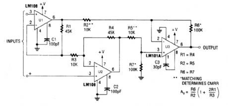
×100INSTRUMENTATION_AMPLIFIER
Published:2009/6/19 4:26:00 Author:May

CMRR vs.frequency. (View)
View full Circuit Diagram | Comments | Reading(508)
AUDIBLE_OUTPUT_INFRARED_RECEIVER
Published:2009/6/19 4:24:00 Author:May
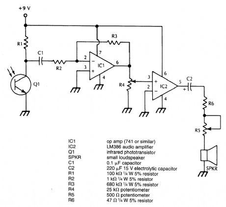
This receiver is designed to demodulate amplitude-modulated (AM) IR light beams and will drive a loudspeaker. R5 is an auxiliary volume control and it could be omitted. Q1 should be suitably mounted and shielded from stray light pickup. (View)
View full Circuit Diagram | Comments | Reading(1022)
SINGLE_TONE_INFRARED_RECEIVER
Published:2009/6/19 4:23:00 Author:May
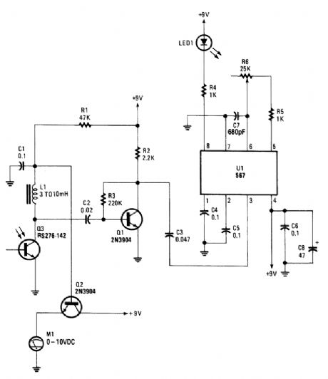
Phototransistor Q3 acts as a sensor that detects modulated IR energy. Q1 is an amplifier and U1 is a tone decoder. LED1 lights on reception of an IR signal with proper tone modulation. (View)
View full Circuit Diagram | Comments | Reading(933)
PULSE_FREQUENCY_MODULATED_IR_TRANSMITTER
Published:2009/6/19 4:21:00 Author:May
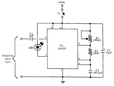
Schematic diagram for the pulse frequency-modulated LED transmitter. Adjust the frequency by rotating R1. With components shown, the frequency range is between 8 and 48 kHz. (View)
View full Circuit Diagram | Comments | Reading(1732)
XS-Ⅱ electronic energy saving switch circuit diagram
Published:2011/5/5 22:59:00 Author:Jessie | Keyword: electronic, energy saving, switch
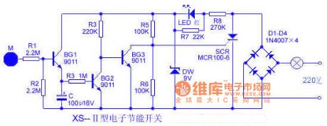
This switch is a touch delay electronic switch. Users touch metal M 1 second,lamp delaylighting 1-2 minutes; Users touch 2 seconds, the lamp ligting ≥ 3 minutes; Users touch 4 seconds, the lamp ligting ≥ 5 minutes.
(View)
View full Circuit Diagram | Comments | Reading(1769)
Automatic dry hands circuit
Published:2011/5/5 23:04:00 Author:Jessie | Keyword: dry hands

This circuit is consists of transimitting and infrared receiving control parts. Infrared transmit partproduces 5kHzfrequency by using 555 time-based circuit, drive infrared tubestransmit infrared light.When hand is under the dryer, because of infrared reflection action, PH302 will receive infrared and change it into electrical signals, by frequency selective amplifier which composed by IC1, IC2,IC3, it's output signal becomes DC signal into IC4 comparator after enlargement, plastic andfiltering. When the input level of IC4 isover 7V, its output changes into low level, trigger IC5 timer starts timing, pin 3 becomes high-level, 3DG130 connected, relay contacts suck close, connect resistance wire and fan.
(View)
View full Circuit Diagram | Comments | Reading(589)
POWER_TRANSFORMER_TESTER
Published:2009/6/19 4:21:00 Author:May
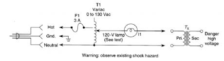
Very often a power transformer is suspect and connecting a shorted transformer to an ac source can be hazardous. This test method will detect a defective or shorted transformer. The primary of the power transformer is energized through a Variac (0 to 130 Vac) and a lamp equal in wattage to about half that of the transformer under test. Connect the transformer, set Variac at zero, then energize cir-cuit. Apply voltage to suspected transformer (Tx) as shown. The lamp should not light. If it does, Tx is shorted. Next, short the secondary of suspected Tx. This time, the lamp should light. For multiple winding transformers, repeat for each secondary winding. Beware of the shock hazard as the open windings of Tx can develop full-rated voltage. (View)
View full Circuit Diagram | Comments | Reading(541)
Quasi-digital amplifier circuit diagram
Published:2011/6/27 1:25:00 Author:Rebekka | Keyword: Quasi-digital amplifier
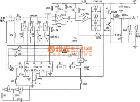
Quasi-digital amplifier. Its power amplification process uses digital means (PWM), and the volume control also is digital. The Sl ~ S4 in the CMOS analog switch CD4066 and the composition of binary reversible counter CD40193 form the digital volume control circuit. Press ANl key, 2Hz clock pulse from the NAND gate H3, H4, and the output of NAND gate H2 turn into CD40193 of CL + side and the CD40193 is counted by addition; When you press AN2 key, the clock pulse of the non-2Hz Gate Bl, B2 enters the CL-end CD40193. The CD40193 is counted by subtraction. (View)
View full Circuit Diagram | Comments | Reading(1817)
High-precision pressure amplifier circuit composed of the AD624
Published:2011/6/27 0:12:00 Author:Rebekka | Keyword: High-precision pressure amplifier


High-precision pressure amplifier circuit is mainly used in small amplification system. The AD624 is a precision low-noise instrumentation amplifier which can be used in a small sensor output signal amplification system. The figure shows the high-precision pressure amplifier circuit composed of the AD624. The sensor is a standard strain gauge bridge sensors. The bridge voltage uses+ 9.00V, potentiometers R8 and R6 to zero, in which R6 is coarse, R8 is fine. The amplifier output can be directly related to high-precision A / D converter connected. (View)
View full Circuit Diagram | Comments | Reading(1640)
WIRELESS_IR_HEADPHONE_RECEIVER
Published:2009/6/19 4:20:00 Author:May
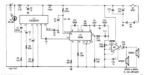
A photodiode D1 feeds high gain IR remote control preamp IC, a CA3237E. U2 is a PLL FM de-tector tuned to around 100 kHz. The detector output is amplified by U3 and it can drive a speaker or a set of headphones. (View)
View full Circuit Diagram | Comments | Reading(3436)
ECG_AMPLIFIER_WITH_RIGHT_LEG_DRIVE
Published:2009/6/19 4:19:00 Author:May
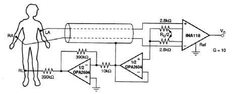
View full Circuit Diagram | Comments | Reading(1943)
| Pages:1397/2234 At 2013811382138313841385138613871388138913901391139213931394139513961397139813991400Under 20 |
Circuit Categories
power supply circuit
Amplifier Circuit
Basic Circuit
LED and Light Circuit
Sensor Circuit
Signal Processing
Electrical Equipment Circuit
Control Circuit
Remote Control Circuit
A/D-D/A Converter Circuit
Audio Circuit
Measuring and Test Circuit
Communication Circuit
Computer-Related Circuit
555 Circuit
Automotive Circuit
Repairing Circuit