
Circuit Diagram
Index 1382
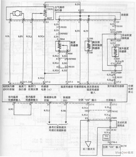
Hyundai Sonata Car Blower And Air Conditioning Control System (Automatic) Circuit (the 3rd)
Published:2011/7/18 4:44:00 Author:Felicity | Keyword: Hyundai Sonata Car, Blower And Air Conditioning, Control System, (Automatic), Circuit, (the 3rd )
View full Circuit Diagram | Comments | Reading(1364)
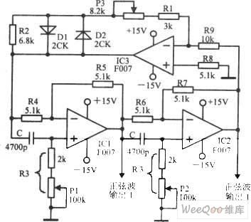
SINE_WAVE_CONVERTER
Published:2009/6/22 23:54:00 Author:Jessie

This circuit produces a sine wave with a low-frequency clock input. The clock rate should be 100Hz or less. (View)
View full Circuit Diagram | Comments | Reading(3290)
HOME_SECURITY_MONITOR_SYSTEM
Published:2009/6/22 23:40:00 Author:May

This circuit provides normally open (NO) and normally closed (NC) contacts S1, S2, and S3 to turn on the alarm after a 30 second delay. S4 and S5 operate instantly. The CANCEL switch resets the alarm. (View)
View full Circuit Diagram | Comments | Reading(640)
Hyundai Sonata Car Blower And Air Conditioning Control System (Automatic) Circuit (the 2nd)
Published:2011/7/18 3:24:00 Author:Felicity | Keyword: Hyundai Sonata Car, Blower And Air Conditioning, Control System, (Automatic), Circuit, (the 2nd)

View full Circuit Diagram | Comments | Reading(1191)
DITHERIZER
Published:2009/6/22 23:54:00 Author:Jessie

In digital audio, a noise signal of amplitude less than one significant bit is often added to the au-dio to reduce the quantizing effect and improve the audio quality by trading digital noise for ana-log noise, which does not have the harsh sound. This circuit consists of a noise generator to add a low level of noise to an analog signal to be digitized, or an analog signal from a digital source. (View)
View full Circuit Diagram | Comments | Reading(1338)
QUAD_TONE_OSCILLATOR
Published:2009/6/22 23:40:00 Author:May

A quad op amp (TL084, etc.) can be used to produce four audio tone generators for use in a test setup. The circuit uses a 12-V supply. (View)
View full Circuit Diagram | Comments | Reading(0)
DRIVEN_FLYBACK_CONVERTER
Published:2009/6/22 23:53:00 Author:Jessie

This circuit uses an SG1524 Silicon General regulating pulse width modulator and provides ±15 V from a 5-V supply rail. (View)
View full Circuit Diagram | Comments | Reading(1367)
TELEVISION_VERTICAL_DEFLECTION_CIRCUIT
Published:2009/6/22 23:40:00 Author:May

Two transistors are used to drive the yoke(2.5 mH + 0.3Ω) in this deflection circuit. R8 samples the yoke current and provides feedback to Q2, resulting in a very linear current ramp through the yoke. (View)
View full Circuit Diagram | Comments | Reading(0)
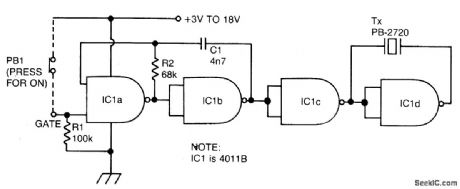
PULSED_TONE_ALARM,GATED_BY_A_HIGH_INPUT,WITH_DIRECT_DRIVE_OUTPUT
Published:2009/6/22 23:53:00 Author:Jessie

View full Circuit Diagram | Comments | Reading(1201)
12_BIT_DAC
Published:2009/6/22 23:52:00 Author:Jessie

This circuit uses an Analog Devices DAC-8043 12-bit multiplying DAC The output will be D/4096×Vref where D is the numerical value of the digital input word(0 to 4095) Vref is 1.235 volts in this cicuit (View)
View full Circuit Diagram | Comments | Reading(1771)
Adjustable Rate Constant Sinusoidal Frequency Oscillator Circuit
Published:2011/7/18 5:40:00 Author:Felicity | Keyword: Adjustable Rate Constant, Sinusoidal Frequency Oscillator, Circuit
Adjustable Rate Constant Sinusoidal Frequency Oscillator Circuit is showed in the picture above. (View)
View full Circuit Diagram | Comments | Reading(564)
EASILY_TUNED_SINE_WAVE_OSCILLATOR
Published:2009/6/22 23:39:00 Author:May

The circuit will provide both a sine-and square-wave output for frequencies from below 20 Hz to above 20 kHz. The frequency of oscillation is easily tuned by varying a single resistor. This is a considerable advantage over Wien bridge circuits, where two elements must be tuned simultaneously to change frequency. Also, the output amplitude is relatively stable when the frequency is changed.An operational amplifier is used as a tuned circuit, driven by square wave from a voltage comparator. Frequency is controlled by R1, R2, C1, C2, and R3, with R3 used for tuning. Tuning the filter does not affect its gain or bandwidth, so the output amplitude does not change with frequency. A comparator is fed with the sine-wave output to obtain a square wave. The square wave is then fed back to the input of the tuned circuit to cause oscillation. Zener diode, D1, stabilizes the amplitude of the square wave fed back to the filter input. Starting is ensured by R6 and C5, which provide dc negative feedback around the comparator. This keeps the comparator in the active region (View)
View full Circuit Diagram | Comments | Reading(0)
CONTINUOUS_TONE_2_kHz_BUZZER_WITH_BRIDGE_DRIVE,GATED_ON_BY_A_LOGIC_0
Published:2009/6/22 23:51:00 Author:Jessie
View full Circuit Diagram | Comments | Reading(710)
VEHICLE_SECURITY_SYSTEM
Published:2009/6/22 23:39:00 Author:May
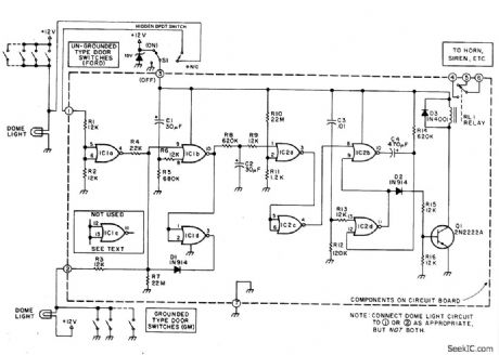
This alarm gives a 15-20 second exit and entrance delay. After being triggered, the alarm sounds for five minutes and then shuts off. Once triggered, the sequence is automatic and is not affected by subsequent opening or closing of doors. (View)
View full Circuit Diagram | Comments | Reading(0)
SIMPLE_INTERCOM_FOR_NOISY_ENVIRONMENTS
Published:2009/6/22 23:51:00 Author:Jessie
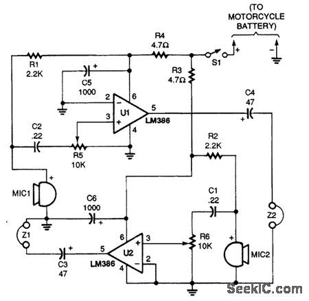
This intercom was originally designed for motorcycle to passenger communications A simple"passenger-to-pilot”ttercom circuit is shown. Two LM386 ICs are connected in a low-gam amplifiercircuit with the headphone output of one paired to the microphone input of the other The microphones are electret elements and the earphones can be of the in-ear type or of the small stereo/monotype that with fit inside a helmet Both amplifiers in the circuit operate at a minimum gain of 20 dB. (View)
View full Circuit Diagram | Comments | Reading(3656)
SIMPLE_HF_RECEIVE_CONVERTER
Published:2009/6/22 23:38:00 Author:May

Designed for CB reception, this crystal-controlled converter uses one 40820 dual-gate MOSFET. The circuit will work with any crystal either 3rd overtone or fundamental, over 1 to 50 MHz. (View)
View full Circuit Diagram | Comments | Reading(0)
AUTO_BURGLAR_ALARM_1
Published:2009/6/22 23:50:00 Author:Jessie

View full Circuit Diagram | Comments | Reading(1030)
SECURITY_ALARM
Published:2009/6/22 23:38:00 Author:May

This alarm features open- and closed-loop detector and automatic alarm shutoff. Offers 15 second exit/entrance delay. Alarm on time can be adjusted from 1 to 15 minutes. (View)
View full Circuit Diagram | Comments | Reading(0)
TTL_BASED_AUDIO_OSCILLATOR
Published:2009/6/22 23:49:00 Author:Jessie

Half a 7404 will produce a tone around 1000 Hz with this circuit. (View)
View full Circuit Diagram | Comments | Reading(3412)
Active / Passive Phono Preamplifier Circuit
Published:2011/7/18 6:00:00 Author:Felicity | Keyword: Active / Passive Phono, Preamplifier Circuit

View full Circuit Diagram | Comments | Reading(1119)
| Pages:1382/2234 At 2013811382138313841385138613871388138913901391139213931394139513961397139813991400Under 20 |
Circuit Categories
power supply circuit
Amplifier Circuit
Basic Circuit
LED and Light Circuit
Sensor Circuit
Signal Processing
Electrical Equipment Circuit
Control Circuit
Remote Control Circuit
A/D-D/A Converter Circuit
Audio Circuit
Measuring and Test Circuit
Communication Circuit
Computer-Related Circuit
555 Circuit
Automotive Circuit
Repairing Circuit