
Circuit Diagram
Index 1385
TEMPERATURE_SENSOR
Published:2009/6/22 23:09:00 Author:May
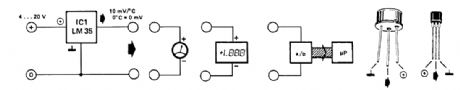
The LM35 temperature sensor provides an output of 10 mV/℃ for every degree Celsius over 0℃. At 20℃ the output voltage is 20 x 10 = 200 mV. The circuit consurnes 60 μA. The load resistance should not be less than 5 kΩ. A 4- to 20-V supply can be used. (View)
View full Circuit Diagram | Comments | Reading(0)
The sensor bridge drive amplifier circuit
Published:2011/7/21 3:03:00 Author:Seven | Keyword: sensor bridge, drive, amplifier circuit
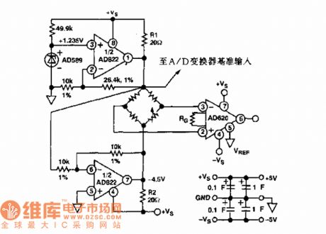
The sensor and AD822 single power supply, power supply forward/backward limit output, low-power FET input computing amplifier circuit. Functions: used in reception office sensor amplifier adjusting, LED preamplifier, medical devices and data collection, etc.
(View)
View full Circuit Diagram | Comments | Reading(636)
SIMPLE_HF_RECEIVE_CONVERTER
Published:2009/6/22 23:38:00 Author:Jessie

Designed for CB reception, this crystal-controlled converter uses one 40820 dual-gate MOSFET. The circuit will work with any crystal either 3rd overtone or fundamental, over 1 to 50 MHz. (View)
View full Circuit Diagram | Comments | Reading(1693)
MONITOR_POWER_SAVER_FOR_COMPUTERS
Published:2009/6/22 23:09:00 Author:May
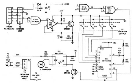
The circuit monitors PC keyboard activity through five-pin DIN connector J1. When the user presses a key, the keyboard sends a series of negative-going pulses on pin 2. In conjunction with Q1 and C3, the op amp essentially functions as an integrator, which stretches the continually varying periods of the input pulses to a relatively constant period with a higher average dc value.Inverters IC1-c and IC1-b buffer the peak detector's output to trigger IC4, an MC14536B programmable timer. (View)
View full Circuit Diagram | Comments | Reading(1802)
The sensor regulation circuit
Published:2011/7/21 3:04:00 Author:Seven | Keyword: sensor regulation circuit
It is used in sensor regulation circuits.
(View)
View full Circuit Diagram | Comments | Reading(489)
EEPROM_PROGRAMMING_DOUBLER_CIRCUIT
Published:2009/6/22 23:08:00 Author:May

Even though electrically erasable PROMs offer the convenience of single-byte write and erase operations, the parts require a somewhat nonstandard programming voltage-21 V. A simple circuit that develops the appropriate voltage from a computer system's standard 12-to-15-Vdc supply, reme-dies the problem nicely. Moreover, it permits the programming voltage to be pulsed under the control of an extemal CPU.As shown in the figure, the chip uses its complementary outputs, Q1 and Q2 to trigger a bridge rectifier through capacitors C2 and C3. Resistors R2 and R3 and diodes Dl and D2limit the current and protect IC1 from spikes from C2 and C3. If required, the regulator will deliver up to 150 mA.Circuit IC3 is an open-collector TTL gate whose output, when low, disables IC2 and causes it to put out 5 Vdc. The regulator delivers the 21-V programming pulse. (View)
View full Circuit Diagram | Comments | Reading(613)
SECURITY_ALARM
Published:2009/6/22 23:38:00 Author:Jessie

This alarm features open- and closed-loop detector and automatic alarm shutoff. Offers 15 second exit/entrance delay. Alarm on time can be adjusted from 1 to 15 minutes. (View)
View full Circuit Diagram | Comments | Reading(1221)
WWV_CONVERTER
Published:2009/6/22 23:37:00 Author:Jessie

This converter heterodynes the 15-MHz WWW signal with a 16-MHz oscillator so that it can be heard at 1 MHz on an ANI broadcast receiver. T1 and T2 are a modified 10.7-MHz IF transformer and AM BO oscillator coil, respectively. (View)
View full Circuit Diagram | Comments | Reading(2131)
REMOTE_TEMPERATURE_SENSING
Published:2009/6/22 23:07:00 Author:May
An AD590 or AD592 makes it easy to transmit temperature data over a pair of wires. The circuit produces 1mV/℃ (or 1mV/°F using the values in parentheses). (View)
View full Circuit Diagram | Comments | Reading(2413)
The sensor AD converter circuit
Published:2011/7/21 2:44:00 Author:Seven | Keyword: sensor, AD converter

The figured AD872 is a 12-bit A/D converter. AD8047 is a general voltage feedback computing amplifier, which inputs impedance.
(View)
View full Circuit Diagram | Comments | Reading(522)
PSEUDOGROUND
Published:2009/6/22 23:37:00 Author:Jessie
For op-amp circuits, a pseudo ground is often needed; a voltage reference IC can be used. The Analog Devices AD780 is used here for this application. This can sink or source current. (View)
View full Circuit Diagram | Comments | Reading(1437)
OP_AMP_RESISTANCE_MULTIPLICATION_CIRCUIT
Published:2009/6/22 23:36:00 Author:Jessie
Equivalent feedback resistance is 10 GΩ, but only standard resistors are used. Even though the offset voltage is multiplied by 100, output offset is actually reduced because error is dependent on offset current, rather than bias current. Voltage on summing junction is less than 5 mV. (View)
View full Circuit Diagram | Comments | Reading(783)
AF_DRIVE_INDICATOR
Published:2009/6/22 23:07:00 Author:May

This circuit was used with an audio power amplifier to detect the point at which output is -3 dB from maximum, indicated by LED D5, and at clipping, shown by LED D6. The indicator can be used with any amplifier operating from a ±30 to ±70V symmetrical supply. (View)
View full Circuit Diagram | Comments | Reading(888)
The bridge sensor over-voltage wave protection circuit
Published:2011/7/21 2:28:00 Author:Seven | Keyword: bridge sensor, protection circuit
View full Circuit Diagram | Comments | Reading(417)
+12_V_FLASH_MEMORY_PROGRAMMING_SUPPLY
Published:2009/6/22 23:07:00 Author:May

The MAX734 can deliver up to 120 mA @12 V from a +5-V supply, using few external compo-nents. This supply can also be used for other applications than memory programming. A logic level is used for shutdown. Efficiency is about 85%. (View)
View full Circuit Diagram | Comments | Reading(706)
SINGLE_CHIP_MESSAGE_SYSTEM
Published:2009/6/22 23:35:00 Author:Jessie

The ISD1016 is a complete analog audio record/playback system on a chip. The analog signal is sampled and the samples stored in an EEPROM as analog levels. Upon playback, the analog data is read out and amplified. Up to 16 seconds of data(audio)can be stored. (View)
View full Circuit Diagram | Comments | Reading(1436)
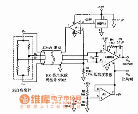
The current sensor applied connector circuit
Published:2011/7/21 2:34:00 Author:Seven | Keyword: current sensor, applied connector

Function: it is used in the current sensor, motor control, accelerating sensor, pressure sensor, position symbol sensor, strain sensor and other low LEV signal source circuits.
(View)
View full Circuit Diagram | Comments | Reading(457)
AUTOMOTIVE_BURGLAR_ALARM
Published:2009/6/22 23:35:00 Author:Jessie

Alarm triggers on after a 13 second delay and stays on for 1-1 1/2 minutes. Then it resets automatically. It can also be turned off and reset by opening and reclosing S1. (View)
View full Circuit Diagram | Comments | Reading(999)
The light isolation data collecting system circuit
Published:2011/7/21 2:35:00 Author:Seven | Keyword: data collecting system
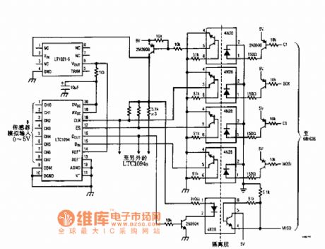
View full Circuit Diagram | Comments | Reading(414)
COMPUTER_POWERED_RS_232
Published:2009/6/22 23:05:00 Author:May

Commercializing battery-operated equipment that must interface to a computer via the RS-232 port runs into the problem of power consumption. To load the system batteries strictly to power the interface is unacceptable. An alternative is to let the computer that the device is connected to pro-vide the interface's power. One snag is that the RS-232 specification doesn't have a power tap on the connector, but it does provide RTS and DTR (request to send and data terminal ready) signals that assert a negative voltage in their quiescent state.Figure 18-GA shows a simple scheme of deriving a 5-V potential from the RTS and DTR signals.R7 and R8 and diodes Dl and D2 mix the return current to the RS-232 port so that the RTS and DTR drivers split the current drawn by the interface. This scheme, even from a laptop computer, can sup-ply 12 rnA to the interface. The only drawback is that the TTL device must be isolated from the cora-puter's ground (earth ground) because the interface treats the RS-232 ground as a positive voltage.A modified optocoupler system shifts the RS-232 level to TTL voltages (Fig. 18-6B). It will sup-port up to 9600 bits/s. C3 is charged up to about 1 V less than the RTS voltage while the TTL line as-serts a marking state. As the capacitor is charging, Q3 is biased into saturation, thus providing a negative voltage (with respect to RS-232 ground) to the RS-232 RXD line. When a spacing bit is driven from the TTL line, Q3 switches off and Q4 switches on. This biases Q4's emitter up to the RS-232 ground. That ground potential is summed with C3's charge to create an RS-232-compatible spacing signal (approximately 1 V less than a -VRTS)The discharge rate on C3 is limited by R15 to prevent the signal sag from becoming a problem down to 110 bits/s. The C2/R1 time constant must be fairly close (within 4 times) to the C3/R15 time constant to ensure that Q3 turns off correctly. (View)
View full Circuit Diagram | Comments | Reading(588)
| Pages:1385/2234 At 2013811382138313841385138613871388138913901391139213931394139513961397139813991400Under 20 |
Circuit Categories
power supply circuit
Amplifier Circuit
Basic Circuit
LED and Light Circuit
Sensor Circuit
Signal Processing
Electrical Equipment Circuit
Control Circuit
Remote Control Circuit
A/D-D/A Converter Circuit
Audio Circuit
Measuring and Test Circuit
Communication Circuit
Computer-Related Circuit
555 Circuit
Automotive Circuit
Repairing Circuit