Circuit Diagram
Index 1396
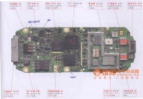
DongXin EL610 mobile phone maintenance circuit diagram
Published:2011/5/6 1:46:00 Author:Jessie | Keyword: mobile phone maintenance
View full Circuit Diagram | Comments | Reading(588)
ATV_VIDEO_SAMPLER_CIRCUIT
Published:2009/6/19 4:39:00 Author:May

This unit picks up your ATV signal by sampling the transmission line with negligible insertion loss. It uses 2 N connectors for input and output connections. A BNC connector is used on the video output. The detected output is connected to your rrtonitor and scope so that you can accu-rately adjust your transmitter for proper video and synch levels. TWo different models are provided.Both have relative power output meters, but one has greater accuracy. There are two PC controls, one for video level and the other for power output. (View)
View full Circuit Diagram | Comments | Reading(815)
SIMPLE_VIDEO_AMPLIFIER
Published:2009/6/19 4:38:00 Author:May
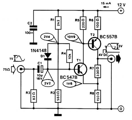
Useful for interfacing B/W TV sets with a camera or computer, this amplifier has a bandwidth of ≥10 MHz and a gain of 3X. (View)
View full Circuit Diagram | Comments | Reading(1138)
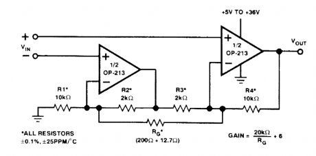
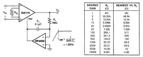
2INSTRUMENTATION_AMPLIFIER
Published:2009/6/19 4:38:00 Author:May
View full Circuit Diagram | Comments | Reading(671)
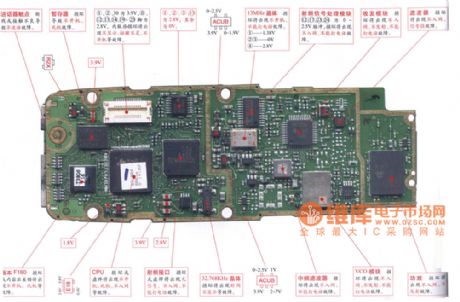
Bodao S1000 mobile phone maintenance circuit diagram
Published:2011/5/6 1:45:00 Author:Jessie | Keyword: mobile phone maintenance
View full Circuit Diagram | Comments | Reading(483)
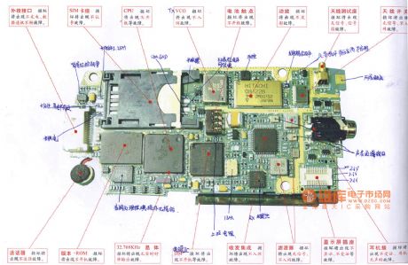
Haier GD268E mobile phone maintenance circuit diagram
Published:2011/5/6 1:44:00 Author:Jessie | Keyword: mobile phone maintenance
View full Circuit Diagram | Comments | Reading(1251)
SIMPLE_HIGH_CURRENT_MEASURER
Published:2009/6/19 4:35:00 Author:May

Testing heavy-load devices with a ten-amp maximum meter can be accomplished with this straightforward meter add-on. If done right, it could be made from a high-current extension cord. J1 and J2 are well-insulated jacks to accept meter probe tips. (View)
View full Circuit Diagram | Comments | Reading(643)
ULTRA_LOW_NOISE_SINGLE_SUPPLY_INSTRUMENTATION_AMPLIFIER
Published:2009/6/19 4:35:00 Author:May
View full Circuit Diagram | Comments | Reading(601)
LOW_POWER_INSTRUMENTATION_AMPLIFIER
Published:2009/6/19 4:34:00 Author:May
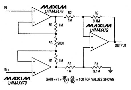
This amplifier requires less than 20 mA from a ±15-V supply. (View)
View full Circuit Diagram | Comments | Reading(633)
Konka 5218 cell phone maintenance circuit diagram
Published:2011/5/6 1:42:00 Author:Jessie | Keyword: cell phone maintenance
View full Circuit Diagram | Comments | Reading(862)
45_MHz_SOUND_IF_AMPLIFIER
Published:2009/6/19 4:34:00 Author:May
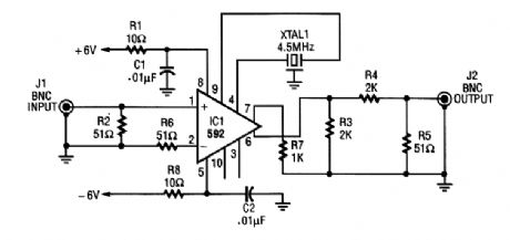
An NE592 is used as a 4.5-MHz amplifier sound subcarrier in video applications. XTAL1 is a 4.5-MHz crystal or ceramic resonator. (View)
View full Circuit Diagram | Comments | Reading(4627)
FOUR_INPUT_MINIMUM_MAXIMUM_SELECTOR
Published:2009/6/19 4:34:00 Author:May

This circuit outputs the maximum (or the minimum) of the four input voltages V1, V2, V3, and V4. Each of these input voltages is in the range 0 to 5V.
The output of the unit is the maximum of V1, V2, V3, and V4 if the control voltage input is 5V (i.e., logical 1). The output is the minimum of V1, V2, V3, and V4 if the control input is zero.
By cascading N such units, one can select the maximum (or the minimum) of 3N + 1 input voltages.
Thus if k is the number of input voltages, we need [(k+1)/3] units. (View)
View full Circuit Diagram | Comments | Reading(743)
Buick headlamps circuit diagram (with the low beam control DRL)
Published:2011/5/6 1:40:00 Author:Jessie | Keyword: headlamps
View full Circuit Diagram | Comments | Reading(617)
Amoi A8 mobile breakdown maintenance circuit diagram
Published:2011/5/6 1:36:00 Author:Jessie | Keyword: mobile maintenance
View full Circuit Diagram | Comments | Reading(3774)
GENERAL_PURPOSE_OUTPUT_AMPLIFIER
Published:2009/6/19 4:33:00 Author:May
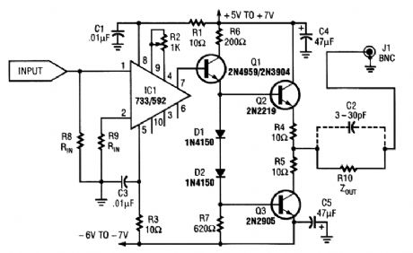
This general-purpose amplifier has a bandwidth of approximately 20 MHz and it uses an LM733/NE592 video amp IC. This circuit can be used as a line driver or as a LAN line driver. (View)
View full Circuit Diagram | Comments | Reading(5509)
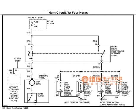
Buick speakers circuit diagram (Four horn)
Published:2011/5/6 1:34:00 Author:Jessie | Keyword: speakers
View full Circuit Diagram | Comments | Reading(509)
LOW_NOISE_INSTRUMENTATION_AMPLIFIER
Published:2009/6/19 4:33:00 Author:May
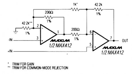
A Maxim MAX412 IC amplifier is used in this circuit. The supply current is ±5 V at 5 mA. (View)
View full Circuit Diagram | Comments | Reading(823)
ac_COUPLED_INSTRUMENTATION_AMPLIFIER
Published:2009/6/19 4:32:00 Author:May
View full Circuit Diagram | Comments | Reading(553)
HIGH_INPUT_IMPEDANCE_INSTRUMENTATION_AMPLIFIER
Published:2009/6/19 4:31:00 Author:May
View full Circuit Diagram | Comments | Reading(1029)
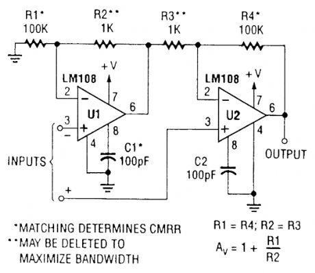
DIFFERENTIAL_NPUT_INSTRUMENTATION_AMPLIFIER
Published:2009/6/19 4:30:00 Author:May
View full Circuit Diagram | Comments | Reading(468)
| Pages:1396/2234 At 2013811382138313841385138613871388138913901391139213931394139513961397139813991400Under 20 |
Circuit Categories
power supply circuit
Amplifier Circuit
Basic Circuit
LED and Light Circuit
Sensor Circuit
Signal Processing
Electrical Equipment Circuit
Control Circuit
Remote Control Circuit
A/D-D/A Converter Circuit
Audio Circuit
Measuring and Test Circuit
Communication Circuit
Computer-Related Circuit
555 Circuit
Automotive Circuit
Repairing Circuit
