Automotive Circuit
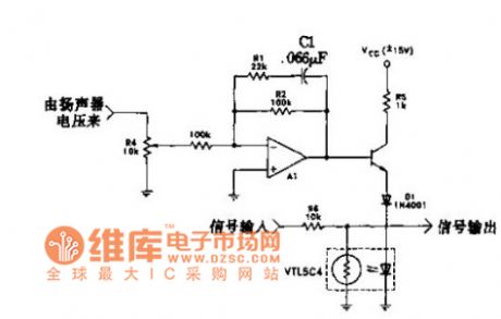
The loudspeaker power amplitude limiter circuit
Published:2011/7/24 7:35:00 Author:Seven | Keyword: power amplitude limiter | From:SeekIC

In the figure is the circuit which utilizes the amplitude limiter to reduce the low frequency power. Under 200HZ, the circuit limits the threshold voltage. When it is low frequency, the amplifier A1 gain is 1. The amplifier is starting when it is 25HZ, the gain is 6Db/octave, and it is cut off, R4 is used to adjust the impedance. VBE of Q1, voltage drop of D1, voltage of LED, they together set the threshold voltage which is 2.8V or so(peak) or 2.0V(RMS). A01 is used to weaken the signal voltage.
Reprinted Url Of This Article:
http://www.seekic.com/circuit_diagram/Automotive_Circuit/The_loudspeaker_power_amplitude_limiter_circuit.html
Print this Page | Comments | Reading(3)

Article Categories
power supply circuit
Amplifier Circuit
Basic Circuit
LED and Light Circuit
Sensor Circuit
Signal Processing
Electrical Equipment Circuit
Control Circuit
Remote Control Circuit
A/D-D/A Converter Circuit
Audio Circuit
Measuring and Test Circuit
Communication Circuit
Computer-Related Circuit
555 Circuit
Automotive Circuit
Repairing Circuit
Code: