
Circuit Diagram
Index 1371
PULSE_ECHO_DRIVER
Published:2009/6/23 2:19:00 Author:May

This pulse-echo driver uses the OPA2662 dual operational transconductance amplifier(OTA)from Burr-Brown(the reeeive circuitry isn't shown). The OTA is preferable over an op amp for driv-ing low impedances because it provides a current output rather than a voltage output.Ultrasonic pulse-echo applications often incorporate a transformer-coupled crystal to obtain a high-voltage pulse because the echo can be orders of magnitude smaller in amplitude. The trans-former turns ratio also provides tuning at the resonant frequency of the crystal, which usually means a relatively low-impedance primary winding.An operational transconductance amplifier(OTA)is preferred over an op amp to drive such a low impedance. One particular application involves a pulse-echo driver circuit using the OPA2662. (View)
View full Circuit Diagram | Comments | Reading(1456)
ADJUSTMENT_FREE_PRECISION_SUMMING_AMPLIFIER
Published:2009/6/23 2:55:00 Author:Jessie
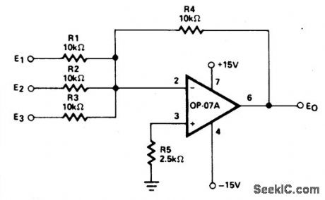
This circuit priduces continuous outputs that are a function of multiple input variables. (View)
View full Circuit Diagram | Comments | Reading(586)
1_A_VOLTAGE_FOLLOWER
Published:2009/6/23 2:53:00 Author:Jessie
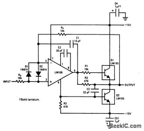
This power voltage follower is good to 300 kHz. (View)
View full Circuit Diagram | Comments | Reading(465)
SLIDE_STEPPER
Published:2009/6/23 2:53:00 Author:Jessie

This stepper circuit replaces remote controls and will automatically advance slides in a projector.The time delay is variable with R4. The cable connections are for a Kodak carousel slide projector. (View)
View full Circuit Diagram | Comments | Reading(1522)
OCTAVE_EQUALIZER
Published:2009/6/23 2:18:00 Author:May

This circuit is one section of an octave equalizer used in audio systems. The table shows the val-ues of C1 and C2 that are needed to achieve the given center frequencies. This circuit is capable of 12 dB boost or cut, as determined by the position of R2. Because of the low input bias current of th,e OP-08, the resistors could be scaled up by a factor of 10, and thereby reduce the values of C1 and C2 at the low-frequency end. In addition, 10 sections will only draw a combined supply current of 6 mA maximum. (View)
View full Circuit Diagram | Comments | Reading(788)
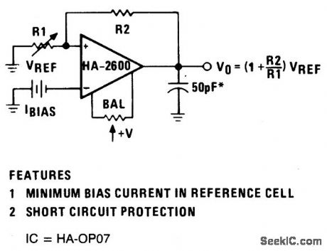
REFERENCE_VOLTAGE_AMPLIFIER
Published:2009/6/23 2:53:00 Author:Jessie
View full Circuit Diagram | Comments | Reading(496)
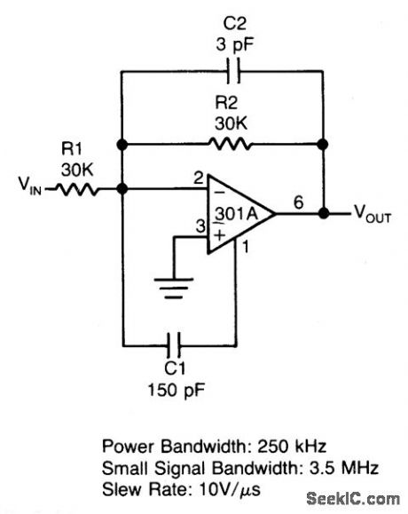
FAST_SUMMING_AMPLIFIER
Published:2009/6/23 2:52:00 Author:Jessie
View full Circuit Diagram | Comments | Reading(470)
GATED_AMPLIFIER
Published:2009/6/23 2:52:00 Author:Jessie
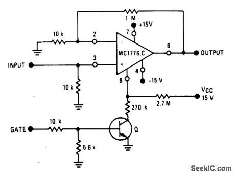
View full Circuit Diagram | Comments | Reading(612)
MODIFIED_HARTLEY_OSCILLATOR
Published:2009/6/23 2:18:00 Author:May

This oscillator uses a tapped coil in the collector circuit, with the tap grounded for the signal. L1 and L2 are coupled inductively and typically have a 3:1 turn ratio, and generally are sections of one entire winding. (View)
View full Circuit Diagram | Comments | Reading(1017)
CHARGER_FOR_PHOTOFLASH_CAPACITOR
Published:2009/6/23 2:51:00 Author:Jessie

This circuit charges photoflash capacitor C (480μF, 500 V) for photoflash usage. (View)
View full Circuit Diagram | Comments | Reading(556)
COLOR_VIDEO_AMPLIFIER
Published:2009/6/23 2:17:00 Author:May

View full Circuit Diagram | Comments | Reading(743)
UNDERWATER_MICROPHONE
Published:2009/6/23 2:17:00 Author:May
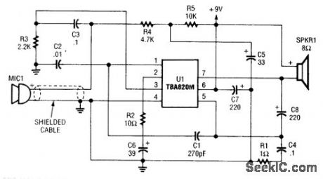
This circuit uses a TBA820 audio IC to amplify underwater sounds. The microphone must be waterproofed. This project was originally used in a home aquarium to monitor fish sounds. (View)
View full Circuit Diagram | Comments | Reading(2283)
455_kHz_OSCILLATOR
Published:2009/6/23 2:17:00 Author:May

The 455-kHz oscillator circuit uses a field-effect transistor (FET)for Q1. The output signal is taken from the source circuit of Q1. T1 is a 455-kHz IF transformer. (View)
View full Circuit Diagram | Comments | Reading(2543)
AUDIO_MEMO_ALERT
Published:2009/6/23 2:16:00 Author:May

This device prevents paper notes and memos from being overlooked. A paper note placed be-tween two fingers made of a conducting material (metal or conductive plastic) breaks the circuit, al-lowing pair 1 of U1-a to go high. This causes U1-c & U1-d to act as an oscillator, pulsing piezo buzzer BZ1. (View)
View full Circuit Diagram | Comments | Reading(517)
NONINVERTING_VOLTAGE_FOLLOWER
Published:2009/6/23 2:16:00 Author:May

View full Circuit Diagram | Comments | Reading(494)
YOUR_NAME_IN_LIGHTS
Published:2009/6/23 2:16:00 Author:May

This circuit will enable you to put a name or callsign in lights using seven-segment LEDs. The display will spell the desired name out sequentially. Select the correct type of LED. Solder the cor-rect leads together to form the letters you want. After mounting the appropriate current-limiting re-sistor, the 7445 can only sink 80 mA, so a PNP transistor is needed to handle the current required to light the letters. The heart of the circuit is a 555 oscillator into a 7490 decade counter, which is de-coded by a 7445 open-collector driver chip. (View)
View full Circuit Diagram | Comments | Reading(635)
LOGARITHMIC_AMPLIFIER_1
Published:2009/6/23 2:51:00 Author:Jessie
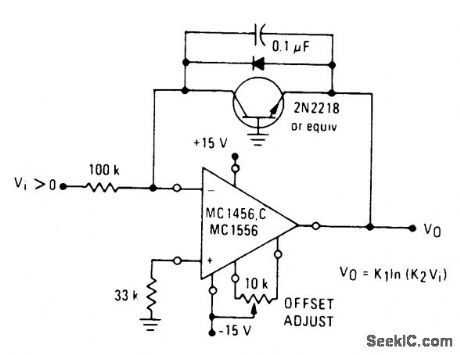
View full Circuit Diagram | Comments | Reading(529)
LOOP_OSCILLATOR_ELIMINATOR
Published:2009/6/23 2:50:00 Author:Jessie

This circuit uses negative feedback to a digital-to-time converter, and can supply a current-con-trolled delay to replace the oscillator in a phase-locked loop that handles input frequencies from 40 kHz to 40 MHz.A current sourced into the inverting input of the op-arrtp integrator's summing node can phase shift the pulses at F in relation to those at E by up to 1800. (View)
View full Circuit Diagram | Comments | Reading(919)
BUTLER_OSCILLATOR_CIRCUIT
Published:2009/6/23 2:15:00 Author:May


This circuit uses an overtone crystal in a Butler oscillator. L1 is approximately 1300μH, and the crystal frequency should be from 20 to 50 MHz. (View)
View full Circuit Diagram | Comments | Reading(1687)
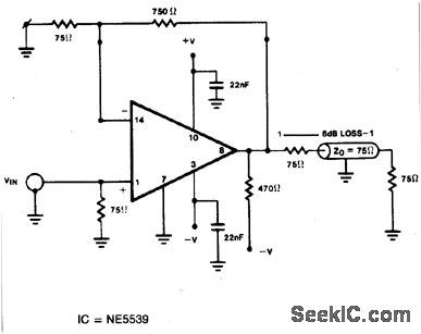
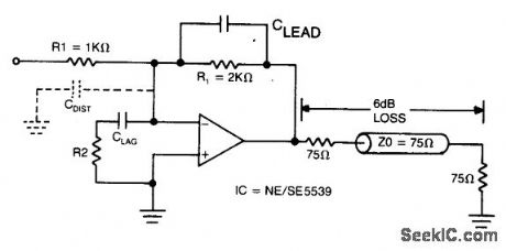
WIDEBAND_UNITY_GAIN_INVERTING_AMPLIFIER_IN_A_75_OHM_SYSTEM
Published:2009/6/23 2:49:00 Author:Jessie
View full Circuit Diagram | Comments | Reading(538)
| Pages:1371/2234 At 2013611362136313641365136613671368136913701371137213731374137513761377137813791380Under 20 |
Circuit Categories
power supply circuit
Amplifier Circuit
Basic Circuit
LED and Light Circuit
Sensor Circuit
Signal Processing
Electrical Equipment Circuit
Control Circuit
Remote Control Circuit
A/D-D/A Converter Circuit
Audio Circuit
Measuring and Test Circuit
Communication Circuit
Computer-Related Circuit
555 Circuit
Automotive Circuit
Repairing Circuit