Signal Processing
Audio oscillator with adjustable frequency composed of μA741
Published:2011/7/28 2:22:00 Author:Ecco | Keyword: Audio oscillator , adjustable frequency | From:SeekIC

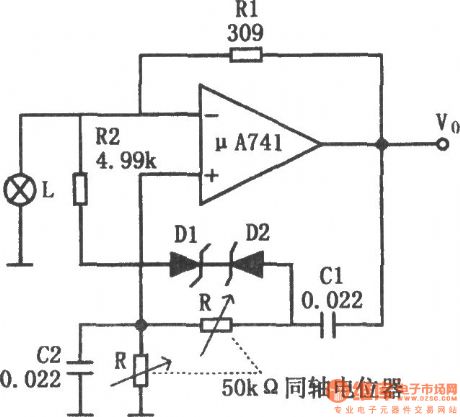
The chart shows the audio oscillator circuit with adjustable frequency. The circuit uses the lamp control circuit gain, but also increases the automatic gain control circuit composed of zener diode D1, D2 and resistor R2. As the frequency dropping, the output amplitude will increase. When the output amplitude increases to a predetermined value, zener diode is conducted, therefore, the amplifier gain reduces, so that it can avoid amplifier saturation. R2 is used to reduce the limiting effect of zener diode to avoid excessive distortion. Increasing R2, D1, D2 can make the adjusting range of oscillation frequency change from the 3:1 to 10:1. Using the components in figure, the oscillation frequency range is 200Hz ~ 2kHz. If R1, C1, C2 select the components with low temperature coefficient, then the temperature changes in the range of -55 ℃ ~ +125 ℃ , frequency stability is ± l%.
Reprinted Url Of This Article:
http://www.seekic.com/circuit_diagram/Signal_Processing/Audio_oscillator_with_adjustable_frequency_composed_of_μA741.html
Print this Page | Comments | Reading(3)

Article Categories
power supply circuit
Amplifier Circuit
Basic Circuit
LED and Light Circuit
Sensor Circuit
Signal Processing
Electrical Equipment Circuit
Control Circuit
Remote Control Circuit
A/D-D/A Converter Circuit
Audio Circuit
Measuring and Test Circuit
Communication Circuit
Computer-Related Circuit
555 Circuit
Automotive Circuit
Repairing Circuit
Code: