
Circuit Diagram
Index 1354
FOUR_CHANNEL_MIXER
Published:2009/6/24 2:23:00 Author:May
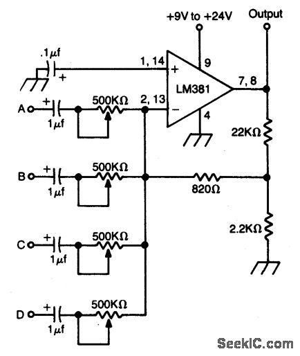
High gain op amp combines up to four individually controlled input signals. The dc power source should be well filtered (battery is ideal), and the circuit should be well shielded to prevent hum pickup. (View)
View full Circuit Diagram | Comments | Reading(1970)
HYBRID_MIXER
Published:2009/6/24 2:22:00 Author:May
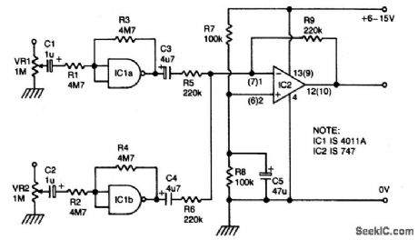
IC1a and b are biased into the linear regions by R3 and R4. (IC1 must be 4011A). Outputs from gates are combined by op amp IC2, which provides low impedance output. (View)
View full Circuit Diagram | Comments | Reading(718)
PHASE_SHIFT_OSCILLATOR
Published:2009/6/24 2:33:00 Author:Jessie

ircuit uses a simple RC network to pro-duce an exceptionally shrill tone from a minia-ture speaker. With the parts values shown, the circuit oscillates at a frequency of 3.6 kHz and drives a miniature 2 1/2 speaker with ear-piercing volume. The output waveform is a square wave with a width of 150 pts, sloping rise and fall times, and a peak-to-peak amplitude of 4.2 volts (when powered by 9 volts). Current drain of the oscillator is 90 mA at 9 volts, and total power dissipation at this voltage is 0.81 watt, which is well below the 1.25 watts the 14-pin version will absorb (at room temperature) before shutting down. (View)
View full Circuit Diagram | Comments | Reading(3310)
SIMPLE_CODE_PRACTICE_OSCILLATOR
Published:2009/6/24 2:33:00 Author:Jessie

With only a minor circuit change, the basic LM3909 oscillator configuration can be turned into a code-practice oscillator. (View)
View full Circuit Diagram | Comments | Reading(1495)
Division Circuit Composed of NE555
Published:2011/7/27 5:38:00 Author:Sue | Keyword: Division Circuit
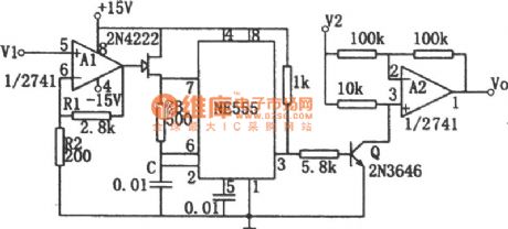
The picture shows the division circuit composed of voltage-frequency converter and amplitude modulator. The input voltage V1 controls field effect tube 2N4222's inner resistance value through operational amplifier A1, so the oscillate frequency of the nonstable multivibrator will be changed.A2 is the amplitude modulator. After the input signal V2 is modulated, it will be output. Presume field effect tube's pinch-off voltage is Vp. If Vp=(1+R1/R2), then the relation between input and output is : Vo=-V2/V1. V1 and V2 are required to have a range of 0-10V. The output Vo is an average value which can be obtained through the filter. It can also be obtained by reading the damped voltmeter. (View)
View full Circuit Diagram | Comments | Reading(520)
WIEN_BRIDGE_SINE_WAVE_OSCILLATOR
Published:2009/6/24 2:32:00 Author:Jessie

Using the 2N5457 JFET as a voltage vari-able resistor in the amplifier feedback loop, produces a low distortion, constant amplitude sine wave getting the amplifier loop gain just right. The LM103 zener diode provides the voltage reference for the peak sine wave amplitude. (View)
View full Circuit Diagram | Comments | Reading(0)
SILENT_AUDIO_SWITCHING_MIXING
Published:2009/6/24 2:21:00 Author:May
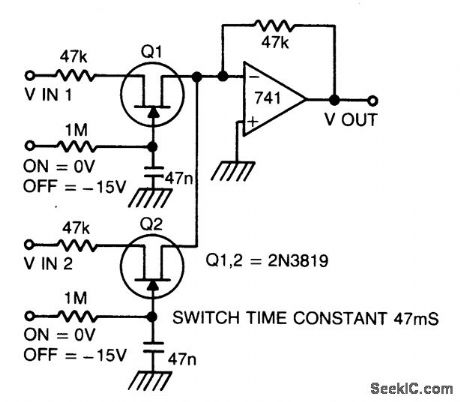
Two or more signals can be switched and/or mixed without annoying clicks by using FETs and a low input-impedance op amp circuit. (View)
View full Circuit Diagram | Comments | Reading(896)
EASILY_TUNED_SINE_SQUARE_WAVE_OSCILLATORS
Published:2009/6/24 2:31:00 Author:Jessie

This circuit will provide both a sine and square wave output for frequencies from below 20 Hz to above 20 kHz. The frequency of oscillation is easily tuned by varying a single resistor. (View)
View full Circuit Diagram | Comments | Reading(1184)
SINE_WAVE_OSCILLATOR
Published:2009/6/24 2:31:00 Author:Jessie

The oscillator delivers a high-purity sinusoid with a stable frequency and amplitude. (View)
View full Circuit Diagram | Comments | Reading(1410)
ONE_TRANSISTOR_AUDIO_MIXER
Published:2009/6/24 2:20:00 Author:May

Three or more inputs with individual level controls feed into the base of Q1 that provides a voltage gain of 20. (View)
View full Circuit Diagram | Comments | Reading(1477)
STABLE_VFO_POWER_SUPPLY
Published:2009/6/24 2:31:00 Author:Jessie

A dc power-distribution system for a stable oscillator should use a separate voltage regulator just for the oscillator circuit. (View)
View full Circuit Diagram | Comments | Reading(558)
dc_POWER_SOURCE_FOR_EXPERIMENTS
Published:2009/6/24 2:30:00 Author:Jessie

This supply uses IC regulators to supply +5, +6, +9, and +12 volts regulated from a nominal 12-V supply. (View)
View full Circuit Diagram | Comments | Reading(1942)
AUDIO_OSCILLATOR
Published:2009/6/24 2:30:00 Author:Jessie

Almost any transistor will work. R1 and C1 will vary the tone. (View)
View full Circuit Diagram | Comments | Reading(330)
CW_IDENTIFIER_WITH_SINE_WAVE_AUDIO_OUTPUT
Published:2009/6/24 2:29:00 Author:Jessie

This identifier can be used to drive a hidden transmitter in a radio fox hunt activity, where the object is to locate a hidden transmitter. (View)
View full Circuit Diagram | Comments | Reading(1714)
MORSE_MESSENGER
Published:2009/6/24 2:19:00 Author:May


This keyer uses a PIC16C54 micro-controller to generate a Morse code message. The microcon-troller must be programmed to suit users call IC or desired message. (View)
View full Circuit Diagram | Comments | Reading(1911)
PASSIVE_MIXER
Published:2009/6/24 2:19:00 Author:May

This simple circuit can be used to combine stereo signals to produce a mnaural output. R1 and R2 isolate both circuits and R3 controls the level of the combined output signal. (View)
View full Circuit Diagram | Comments | Reading(754)
MIXER_PREAMPLIFIER_WITH_TONE_CONTROL
Published:2009/6/24 2:17:00 Author:May

General purpose preamplifier/mixer accepts up to four inputs, has a gain of 1600, and provides bass and treble controls that can be varied ±10 dB at 100 kHz resectively. IC1 and IC2 = LM301A. (View)
View full Circuit Diagram | Comments | Reading(883)
ACTIVE_CW_AUDIO_FILTER
Published:2009/6/24 2:16:00 Author:May

The audio filter shown has a bandpass of 200 Hz centered on 700 Hz. Resistors are 1% tolerance and capacitors should be 5% tolerance. (View)
View full Circuit Diagram | Comments | Reading(842)
CMOS_MIXER
Published:2009/6/24 2:13:00 Author:May

Four inputs can be mixed by duplicating the circuit to the left of C3 and using the fourth gate of IC1. Two gates are used in a touch-operated switching circuit that controls the voltage on the base of switching transistor Q2. Touching TP1 and TP2 alternately turns the circuit on and off. (View)
View full Circuit Diagram | Comments | Reading(641)
TWO_CHANNEL_PANNING_CIRCUIT
Published:2009/6/24 2:12:00 Author:May

This panning circuit (short for panoramic control circuit) provides the ability to move the apparent position of one microphone's input between two output channels. This effect is oftern required in recording studio mixing consoles. Panning is how recording engineers manage to pick up your favorite pianist and float the sound over to the other side of the stage andback again. (View)
View full Circuit Diagram | Comments | Reading(2027)
| Pages:1354/2234 At 2013411342134313441345134613471348134913501351135213531354135513561357135813591360Under 20 |
Circuit Categories
power supply circuit
Amplifier Circuit
Basic Circuit
LED and Light Circuit
Sensor Circuit
Signal Processing
Electrical Equipment Circuit
Control Circuit
Remote Control Circuit
A/D-D/A Converter Circuit
Audio Circuit
Measuring and Test Circuit
Communication Circuit
Computer-Related Circuit
555 Circuit
Automotive Circuit
Repairing Circuit