
Circuit Diagram
Index 1344
TRANSDUCER_AMPLIFIER
Published:2009/6/24 3:31:00 Author:May
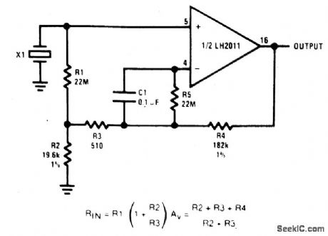
This circuit is high-input-impedance acamplifier for a piezoelectric transducer. Input resistance is 880 M, and again of 10 isobtained. (View)
View full Circuit Diagram | Comments | Reading(683)
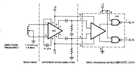
DISC_TAPE_PHASE_MODULATED_READBACK_SYSTEMS
Published:2009/6/24 3:44:00 Author:Jessie
View full Circuit Diagram | Comments | Reading(1012)
AM_RADIO
Published:2009/6/24 3:31:00 Author:May

A IS4 regenerative detector feeds an LM386 audio IC (IC1). 1.5-V D cells and three 9-V batteries are used for a power supply. (View)
View full Circuit Diagram | Comments | Reading(0)
TELEPHONE_LINE_TESTER
Published:2009/6/24 3:30:00 Author:May
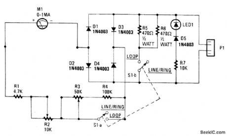
The telephone-line tester shown in the figure is connected to the telephone line through modular connector P1. Because the tester's LED polarity indicator is always connected when the tester is plugged in, the instant that the unit is connected, you will have an indication of the polarity. If it is correct-that is, if the green wire is the positive side and the red wire is the negative side-nothing will happen. If the situation is reversed, the LED will light.With switch S1 set for LINE/RING, both S1-a and S1-b are open and the meter indicates the con-dition of the line voltage. Any line-voltage reading in the LINE Ok range (more on the meter in a rno-ment) indicates a tine voltage that is higher than 40 Vdc. If the telephone is caused to ring, either by using a ringback number or by dialing from another phone, the meter will indicate RING Ok, and the LED will pulse (indicating ac), if the ringing voltage/current is correct. The actual position of the me-ter's pointer depends on how many ringers are connected across the line.When S1 is closed the voltage range of the meter is changed and a nominal load resistance of 230 Ω (R5 and R6) is connected across the line to emulate the off-hook load of the telephone. If the meter indicates LOOP Ok, you can be certain that you have sufficient loop voltage for satisfactory telephone operation. If you place another load on the line, perhaps by taking an extension telephone off hook, the meter reading will almost invariably drop below the LOOP Ok range. If lifting the hand-set causes the meter reading to drop;you can at least be certain that the telephone's hook switch is working and that the repeat coil is connected to the line. (View)
View full Circuit Diagram | Comments | Reading(0)
PHONE_HELPER
Published:2009/6/24 3:44:00 Author:Jessie

This phone-line simulator uses a 60-Hz transformer instead of a ring generator. The dial tone is provided by an NE555 astable oscillator. (View)
View full Circuit Diagram | Comments | Reading(4493)
ELECTRONIC_BALANCED_INPUT_MICROPHONE_AMPLIFIER
Published:2009/6/24 3:30:00 Author:May
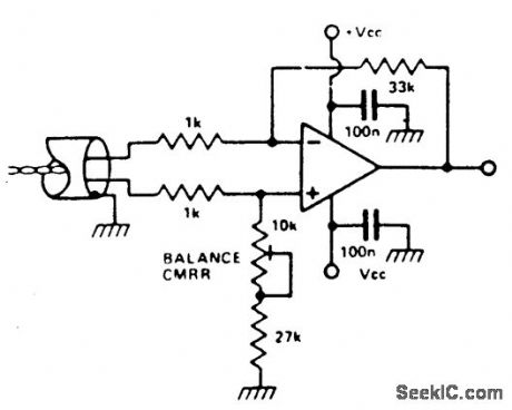
It is possible to simulate the balanced per-formance of a transformer electronically with a different amplifier. By adjusting the presets, the resistor ratio can be balanced so that the best CMRR is obtained. It is possible to get a better CMRR than from a transformer. Use a RC4136 which is a quad low noise op amp. (View)
View full Circuit Diagram | Comments | Reading(780)
BASIC_TRANSISTOR_AMPLIFIER_CIRCUITS
Published:2009/6/24 3:29:00 Author:May
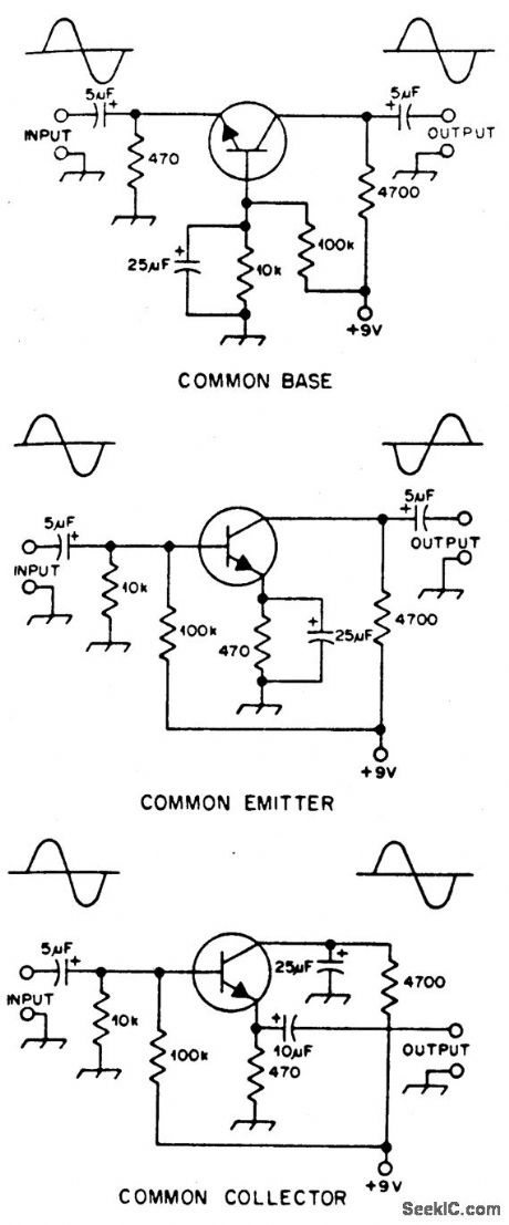
Typical component values are given for use at audio frequencies, where these circuits are used most often. The input and output phase relationships are shown. (View)
View full Circuit Diagram | Comments | Reading(627)
ION_DETECTOR
Published:2009/6/24 3:28:00 Author:May

ANT1 is a short whip antenna from a junked radio or other device. R3 is adjusted to bring the meter on scale. This device should be grounded to operate properly. A length of aluminum or copper foil tape attached to the instrument case makes contact with the hand, and the body senres as a ground via hand contact with this tape. (View)
View full Circuit Diagram | Comments | Reading(0)
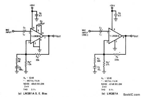
TRANSFORMERLESS_MICROPHONE_PREAMPS_UNBALANCED_INPUTS
Published:2009/6/24 3:40:00 Author:Jessie
View full Circuit Diagram | Comments | Reading(533)
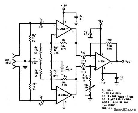
TRANSFORME_RLESS_BALANCE_INPUTS_MICROPHONE_PREAMP
Published:2009/6/24 3:39:00 Author:Jessie
View full Circuit Diagram | Comments | Reading(0)
TELEPHONE_AUDIO_INTERFACE
Published:2009/6/24 3:39:00 Author:Jessie

The telephone audio interface-essentially, a simple isolation/couple circuit-isolates the phone line from any connected audio circuit without presenting any danger to the phone line, the equip-rnent, or the user. (View)
View full Circuit Diagram | Comments | Reading(5440)
BISTABLE_MULTIVIBRATOR
Published:2009/6/24 3:38:00 Author:Jessie
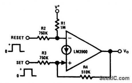
Positive feedback is provided by resistor R4, which causes the latching. A positive pulse at the set input causes the output to go high and a reset positive pulse will return the output to es-sentially 0 Vdc. (View)
View full Circuit Diagram | Comments | Reading(2446)
PHOTORECEIVER_OPTIMIZED_FOR_NOISE_AND_RESPONSE
Published:2009/6/24 3:28:00 Author:May

View full Circuit Diagram | Comments | Reading(618)
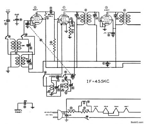
ac/dc_VACUUM_TUBE_AM_AND_SHORTWAVE_RECEIVER
Published:2009/6/24 3:38:00 Author:Jessie


This circuit was used in a World War II vintage AM/SW(6 to 18 MHz)recelver and shows typical circuits used in recelvers at that time. (View)
View full Circuit Diagram | Comments | Reading(1574)
SYNCHRONIZER_CIRCUIT
Published:2009/6/24 3:28:00 Author:May

This common synchronization method uses two rippled 74LS74 D-type flip-flops. (View)
View full Circuit Diagram | Comments | Reading(664)
BELL_SYSTEM_202_DATA_ENCODER
Published:2009/6/24 3:38:00 Author:Jessie

The AD537 is well-suited for frequency-shift modulator and demodulator applications. Requir-ing little power, it is especially appropriate for using phone-line power. The Bell-System 202 data en-coder shown here delivers the mark frequency of 1.2 kHz with the data input low. When the input goes high, the timing current increases to 165 μA and generates the space frequency of 2.2 kHz. The trim shown provides a ±10% range of frequency adjustment. The output goes to the required band-pass filter before transmission over a public telephone line. A complementary demodulator is easy to implement. (View)
View full Circuit Diagram | Comments | Reading(1118)
GENERAL_PURPOSE_PREAMPLIFIER
Published:2009/6/24 3:28:00 Author:May

Not much can be said about how the LM382 works as most of the circuitry is contained within the IC. Most of the frequency-determining components are on the chip-only the capacitors are mounted externally. The LM382 has the convenient characteristic of rejecting ripple on the supply line by about 100 dB, thus greatly reducing the quality requirment for the power supply. (View)
View full Circuit Diagram | Comments | Reading(2508)
SYNC_STRETCHER_CIRCUIT
Published:2009/6/24 3:27:00 Author:May

Q1, Q2, and Q3 comprise a simple video amplifier and sync stretch circuit. Transistor Q1 sync strips the incoming video, which is amplified and mixed with the stripped sync in Q2. Q3 supplies in-version and video amplitude control. (View)
View full Circuit Diagram | Comments | Reading(1403)
TELEPHONE_SCRAMBLER
Published:2009/6/24 3:36:00 Author:Jessie

This circuit uses the usual speech inversion algorithm, implementing it with a COM9046 ASIC. This unit is designed to fit be-Lween the handset and base of a standard telephone. It is powered by a 9-V battery. (View)
View full Circuit Diagram | Comments | Reading(2713)
ASTABLE_MULTIVIBRATOR_WITH_STARTING_NETWORK
Published:2009/6/24 3:35:00 Author:Jessie

This circuit will start with a slowly rising supply voltage waveform. (View)
View full Circuit Diagram | Comments | Reading(0)
| Pages:1344/2234 At 2013411342134313441345134613471348134913501351135213531354135513561357135813591360Under 20 |
Circuit Categories
power supply circuit
Amplifier Circuit
Basic Circuit
LED and Light Circuit
Sensor Circuit
Signal Processing
Electrical Equipment Circuit
Control Circuit
Remote Control Circuit
A/D-D/A Converter Circuit
Audio Circuit
Measuring and Test Circuit
Communication Circuit
Computer-Related Circuit
555 Circuit
Automotive Circuit
Repairing Circuit