
Circuit Diagram
Index 1343
TELEPHONE_AUDIO_INTERFACE
Published:2009/6/24 3:39:00 Author:May

The telephone audio interface-essentially, a simple isolation/couple circuit-isolates the phone line from any connected audio circuit without presenting any danger to the phone line, the equip-rnent, or the user. (View)
View full Circuit Diagram | Comments | Reading(0)
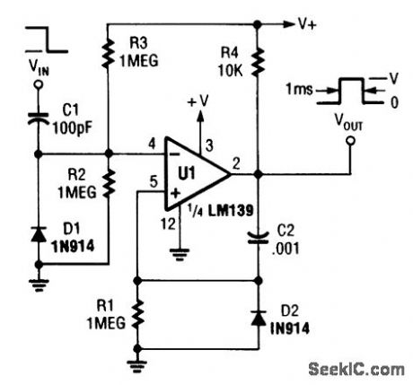
ONE_SHOT_MULTIVIBRATOR
Published:2009/6/24 3:49:00 Author:Jessie


An LM139 section can be used as a one shot (View)
View full Circuit Diagram | Comments | Reading(1964)
BISTABLE_MULTIVIBRATOR
Published:2009/6/24 3:38:00 Author:May
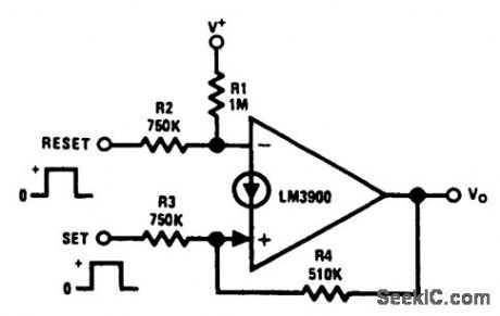
Positive feedback is provided by resistor R4, which causes the latching. A positive pulse at the set input causes the output to go high and a reset positive pulse will return the output to es-sentially 0 Vdc. (View)
View full Circuit Diagram | Comments | Reading(0)
ac/dc_VACUUM_TUBE_AM_AND_SHORTWAVE_RECEIVER
Published:2009/6/24 3:38:00 Author:May


This circuit was used in a World War II vintage AM/SW(6 to 18 MHz)recelver and shows typical circuits used in recelvers at that time. (View)
View full Circuit Diagram | Comments | Reading(0)
BELL_SYSTEM_202_DATA_ENCODER
Published:2009/6/24 3:38:00 Author:May

The AD537 is well-suited for frequency-shift modulator and demodulator applications. Requir-ing little power, it is especially appropriate for using phone-line power. The Bell-System 202 data en-coder shown here delivers the mark frequency of 1.2 kHz with the data input low. When the input goes high, the timing current increases to 165 μA and generates the space frequency of 2.2 kHz. The trim shown provides a ±10% range of frequency adjustment. The output goes to the required band-pass filter before transmission over a public telephone line. A complementary demodulator is easy to implement. (View)
View full Circuit Diagram | Comments | Reading(0)
ELECTRONIC_THERMOSTAT
Published:2009/6/24 3:48:00 Author:Jessie
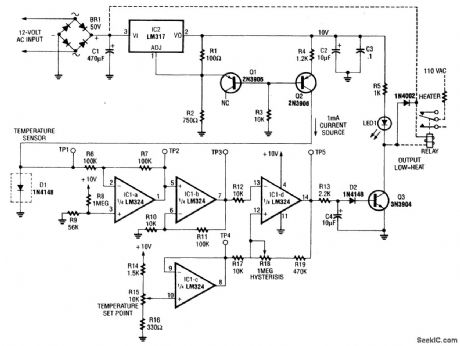
Using a 1N914 diode as a temperature sensor, this straightforward circuit has hysteresis and set-point adjustments. Usable range is about -50 to +150℃. (View)
View full Circuit Diagram | Comments | Reading(2613)
TELEPHONE_SCRAMBLER
Published:2009/6/24 3:36:00 Author:May

This circuit uses the usual speech inversion algorithm, implementing it with a COM9046 ASIC. This unit is designed to fit be-Lween the handset and base of a standard telephone. It is powered by a 9-V battery. (View)
View full Circuit Diagram | Comments | Reading(0)
AM_FM_RECEIVER_CIRCUIT
Published:2009/6/24 3:48:00 Author:Jessie
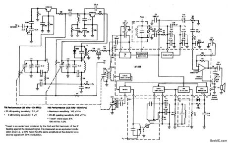
This circuit shows the LM1868 as a complete AM radio and FM IF section. An extemal FM front end is used for the 88- to 108-MHz band. Audio output is 0.5 W and either 9-V battery or line operated supply can be used. (View)
View full Circuit Diagram | Comments | Reading(1704)
ASTABLE_MULTIVIBRATOR_WITH_STARTING_NETWORK
Published:2009/6/24 3:35:00 Author:May

This circuit will start with a slowly rising supply voltage waveform. (View)
View full Circuit Diagram | Comments | Reading(1074)
TELEPHONE_CALL_RESTRICTOR
Published:2009/6/24 3:34:00 Author:May

This circuit is designed to restrict phone calls with the area codes: 900, 976, and 540. This device uses a microcontroller to compare the DTMF decoded tones with telephone numbers stored in EEP-ROM (IC3). This device requires a programmed microcontroller. Software and details of program-ming can be found in the original magazine article. (View)
View full Circuit Diagram | Comments | Reading(0)
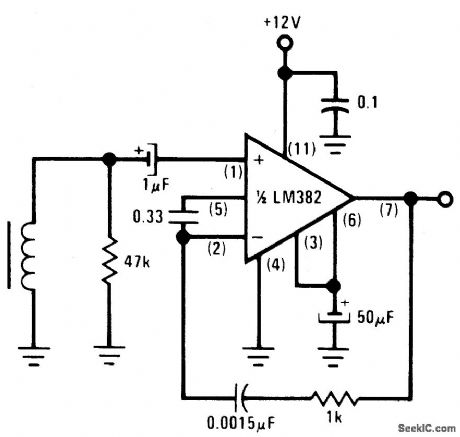
LM382_PHONO_PREAMPLIFIER_RIAA
Published:2009/6/24 3:47:00 Author:Jessie
View full Circuit Diagram | Comments | Reading(751)
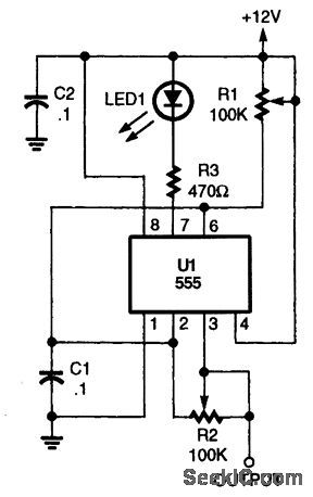
BASIC_555_ASTABLE_MULTIVIBRATOR
Published:2009/6/24 3:47:00 Author:Jessie
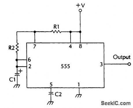
F=1.44(R1=2R2)C1 (View)
View full Circuit Diagram | Comments | Reading(990)
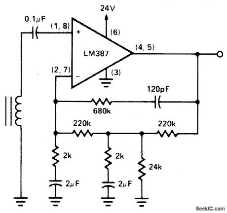
TWO_POLE_FAST_TURN_ON_NAB_TAPE_PERAMPLIFIER
Published:2009/6/24 3:47:00 Author:Jessie
View full Circuit Diagram | Comments | Reading(588)
CALLER_ID_CIRCUIT
Published:2009/6/24 3:33:00 Author:May

This circuit requires programming of the microcontroller. Software information is available from the reference in the original article. (View)
View full Circuit Diagram | Comments | Reading(0)
TELEPHONE_HOLD_CIRCUIT
Published:2009/6/24 3:46:00 Author:Jessie

When the hold button S1 is pressed, SCR1 fires via R1 and R2, firing SCR1, and seizing the line via the path through R3, D1, and SCR1. (View)
View full Circuit Diagram | Comments | Reading(0)
ULTRA_HIGH_GAIN_AUDIO_AMPLIFIER
Published:2009/6/24 3:33:00 Author:May
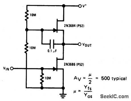
Sometimes called the JFET μt-amp, this circuit provides a very low power, high gain amplifying function. Since pt of a JFET in-creases as drain current decreases, the lower drain current is, the more gain you get. Input dynamic range is sacrificed with increasing gain, however. (View)
View full Circuit Diagram | Comments | Reading(2355)
TELEPHONE_RING_SIGNAL_DETECTOR
Published:2009/6/24 3:45:00 Author:Jessie

Discrirrtinating between telephone-ring signals on a phone line can be accomplished by using dedicated ICs, such as AT&T's LB1006AB or Texas Instruments' TMS1520A. However, if the system already is using a microcontroller, those dedicated chips can be replaced with simpler hardware and a few bytes of code.Looking at the setup, the ringing voltage pulses the optoisolator's LED, which, in turn, pulses the low-asserted RD line to the microcontroller. The firmware analyzes the pulses to determine whether a valid ringing signal is present.The frequency limits of a valid signal are 20 to 80 Hz, which is modulated 2 seconds on and 4 sec-onds off (with distinctive ringing, though, this cadence can vary). Therefore, the simplest analysis is to count down at least 20 pulses of RD in 1 second.The routine could be expanded to determine what type of ring signal is present in a distinctive ring setting. Such a system could switch the phone line to various output jacks. As a result, several phone devices could use the same line without first picking up the line to determine if it's avoice, fax, or data call. (View)
View full Circuit Diagram | Comments | Reading(3380)
SHORTWAVE_RECEIVER
Published:2009/6/24 3:45:00 Author:Jessie
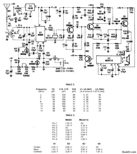
This receiver covers 8.5 to 11.5 MHz in two bands and has a sensitivity of under 1 μV. Nn NE602 mixer feeds a 455-kHz IF amplifier (Q1 and Q2), detector D4, and audio amplifier IC2. Q4 serves as an AGC amplifier coil data is given in the table. The LO is varactor tuned. (View)
View full Circuit Diagram | Comments | Reading(3429)
ASTABLE_WITH_VARIABLE_PULSE_WIDTH
Published:2009/6/24 3:44:00 Author:Jessie
This produces a positive variable width pulse and has a symmetry control. R1 and R2 control the pulse width and symmetry. (View)
View full Circuit Diagram | Comments | Reading(1447)
MOTOR_DIRECTION_CONTROL
Published:2009/6/24 3:32:00 Author:May
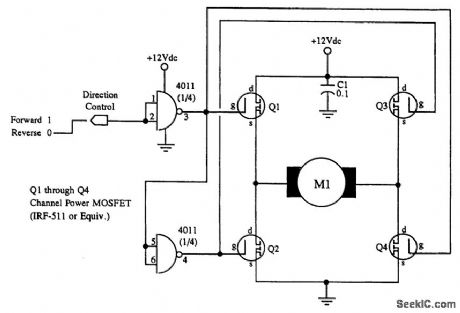
M1 is a small hobby dc motor. (View)
View full Circuit Diagram | Comments | Reading(1239)
| Pages:1343/2234 At 2013411342134313441345134613471348134913501351135213531354135513561357135813591360Under 20 |
Circuit Categories
power supply circuit
Amplifier Circuit
Basic Circuit
LED and Light Circuit
Sensor Circuit
Signal Processing
Electrical Equipment Circuit
Control Circuit
Remote Control Circuit
A/D-D/A Converter Circuit
Audio Circuit
Measuring and Test Circuit
Communication Circuit
Computer-Related Circuit
555 Circuit
Automotive Circuit
Repairing Circuit