
Circuit Diagram
Index 1355
HIGH_LEVEL_FOUR_CHANNEL_MIXER
Published:2009/6/24 2:07:00 Author:May

To provide good signal-to-noise ratio,this four channel mixer amplifier controls the signal levels after the amplifiers,and then mixes them to offer a combined output. The circuit works with any 50 ohm to 50 K dynamic microphone but not with crystal or ceramic mikes because the IC input impedance is low. Note that all four circuits are identical but that only one is shown complete. (View)
View full Circuit Diagram | Comments | Reading(892)
FOUR_INPUT_STEREO_MIXER
Published:2009/6/24 2:05:00 Author:May

Four (or more) inputs can be mixed and produce stereo output. Gain of each stage can be boosted by adding RX, but it should be kept below 50 (RX above 2.2 K) to avoid poor fre-quency, response. If more than four stages are used, decrease RX to 6.8 K for six inputs, or 4.7 K for eight inputs. The op amps are 741 or other lower noise types. The power supply circuit is also given. (View)
View full Circuit Diagram | Comments | Reading(817)
Instrument and Signal Circuit Principle Diagram of Liberation CA6400 Series Light Buses
Published:2011/7/22 21:54:00 Author:Michel | Keyword: Liberation, Light Buses, Instrument, Signal, Principle Diagram

Picture:Instrument and Signal Circuit Principle Diagram of Liberation CA6400 Series Light Buses
29-manual indication lights,30-switch of manual indication lights,31-hydraulic warning lights ,32-hydraulic alarm switch,33-temperature sensor,34-fuel table sensor,35-temperature table,36-fuel table,,37and 38-backup light,39-switch of backup light,40-horn relays,41and 42-horn button,43 and 44- claxon. (View)
View full Circuit Diagram | Comments | Reading(746)
NOISE_GENERATOR
Published:2009/6/24 2:04:00 Author:May

This circuit generates noise pulses that are suitable for test purposes, etc. A zener diode is used as a noise source. IC1 is a relaxation oscillator. P1 determines noise bandwidth, and P2 and P3 the noise amplification. Current consumption is 10 mA @ 12 Vdc. (View)
View full Circuit Diagram | Comments | Reading(4)
12V-24V Voltage Conversion Start System Circuit of Toyota Coaster
Published:2011/7/22 21:52:00 Author:Michel | Keyword: Toyota Coaster, Voltage Conversion , Start System Circuit

Fifth,12V-Z4V Voltage Conversion Start System
Coaster coach circuit often uses 12 V system or 24 V system. Some models are 12 V system but they adopt 24 V to start the machine.24V starter is used when the 12V diesel engine feels that 12V start power is not enough.If other electrical system such as generator, electrical equipment are still 12 V,two batteries are needed. 1 and 2 are usually in a parallel state,they bear 12 V generator charge or provide power supply for 12 V power equipment system.When it starts up, two batteries voltage conversion relay reach a 24 V in series way and provide power supply to the starter.When starting is over, voltage conversion relay makes two batteries become parallel connetcion way. And the circuit connection is shown as figure 7.
(View)
View full Circuit Diagram | Comments | Reading(2395)
PROGRAMMABLE_ATTENUATOR_1_TO_00001
Published:2009/6/24 2:03:00 Author:May

View full Circuit Diagram | Comments | Reading(591)
Sub-ultrasonic Remote Control Switch(NE555,LM567,CD4013) Circuit
Published:2011/7/29 5:47:00 Author:Sue | Keyword: Sub-ultrasonic, Remote Control
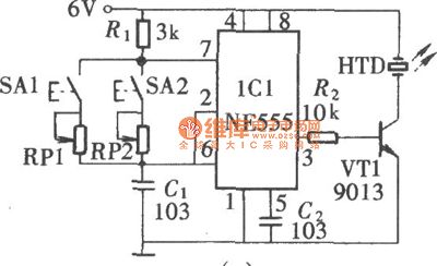
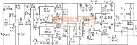
Signal with a frequency higher than 20kHz always can't be heard by human ears, so it is called ultrasonic wave. But in fact, signals with a frequency between 18-20kHz is also hard for human ears to recognise, espacially for those with small transmitting power, which is hardly heard by human ears. So signalsin this range is also called sub-ultrasonic signal. By using sub-ultrasonic signal as remote control signal, special ultrasonic receiver and transmitter are not needed, and human hearings will not be disturbed, so it is very economic and convenient. (View)
View full Circuit Diagram | Comments | Reading(2386)
DIGITALLY_CONTROLLED_AMPLIFIER_ATTENUATOR
Published:2009/6/24 2:02:00 Author:May
View full Circuit Diagram | Comments | Reading(436)
QUAD_POWER_SUPPLY
Published:2009/6/24 2:01:00 Author:May

View full Circuit Diagram | Comments | Reading(1191)
EXPERIMENTER’s_POWER_SUPPLY
Published:2009/6/24 2:00:00 Author:May

Passive linear IC regulators are used to make up a supply delivering +12, +9, +5, -5, -9, and -12 Vdc. T1 and T2 are 12-V, 3-A transformers. (View)
View full Circuit Diagram | Comments | Reading(539)
VARIABLE_ATTENUATOR
Published:2009/6/24 2:00:00 Author:May

The PN4391 provides a low Rds(on) (less than 30 ohms). The tee attenuator provides for optimum dynamic linear range for attenuation and if complete turn-off is desired, attenuation of greater than 100 dB can be obtained at 10 MHz providing proper rf construction techniques are employed. (View)
View full Circuit Diagram | Comments | Reading(796)
TOP_OCTAVE_GENERATOR
Published:2009/6/24 1:59:00 Author:May
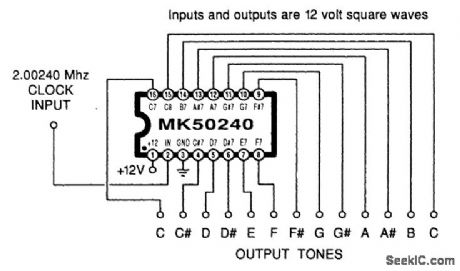
Using an MK50240, this circuit produces 12 top octave tones. The input and output lines can be divided using a binary divider IC to obtain the lower notes. (View)
View full Circuit Diagram | Comments | Reading(1481)
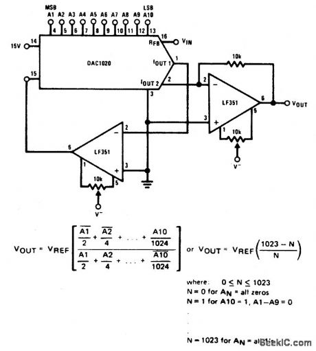
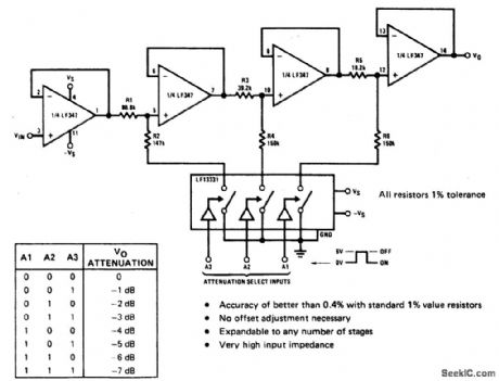
DIGITALLY_SELECTABLE_PRECISION_ATTENUATOR
Published:2009/6/24 1:58:00 Author:May
View full Circuit Diagram | Comments | Reading(667)
THREE_IC_LOW_COST_A_D_CONVERTER
Published:2009/6/24 1:57:00 Author:May

View full Circuit Diagram | Comments | Reading(834)
CXA1642P Song Elimination Integrated Circuit
Published:2011/7/22 21:52:00 Author:Michel | Keyword: Elimination Integrated Circuit
CXAI642P is karaoke songs elimination integrated circuit produced by SONY and it is mainly used in TV
acoustics and audio etc.
First,CXAI642P Typical Application Circuit
CXAI642P intergrated block typical application circuit is shown as the picture 1.Picture 1:CXAI642P Intergrated Block Typical Application Circuit
Second,CXAI642P Pins Functions and DataIntegrated circuit CXAI642P uses 8 feet DIP encapsulation structure, and its integrated circuit pins functions and data are shown as table 1.
Table 1:CXAI642P Pins Functions and Data
Third,Ciruit Work ProcessR accompaniment and singing enters CXA1642P feet ① after the capacitance coupling.L accompaniment and singing enters CXA1642P feet ⑧ after the capacitance coupling.And the accompanying song is eliminated after it is solved.
(View)
View full Circuit Diagram | Comments | Reading(396)
Monolithic Stereophonic Receiver Integrated Circuit of CXA1129N
Published:2011/7/22 21:51:00 Author:Michel | Keyword: Receiver Integrated Circuit

CXA1129N is monolithic stereophonic receiver integrated circuit produced by Sony.It integrates the am, FM stereo radio functions.And it saves power which can be used for one month with one A battery.
First,CXA1129N typical work voltage is 1.5V and the work current is 8mA.
Second,CXA1129N integrated block inside circuit block diagram is shown as figure 1. Figure 1 CXA1129N insdie circuit block diagram of integrated block and typical application circuit.
Third,Pins Functions and Data
CXA1129N uses 30 feet double row flat type plastic package with small size,the length is 10 mm and the width is 5.5 mm/ (View)
View full Circuit Diagram | Comments | Reading(3266)
10A Power Amplifier Circuit
Published:2011/7/13 20:16:00 Author:Sue | Keyword: Power, Amplifier
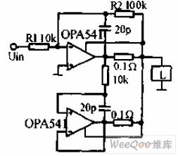
The 10A power amplifier uses two high power operational amplifiers OPA541 which can acquire continuous output of 10A. Theupper one is phase reversal amplifier while theunder one is connected with unit gain circuit. For the load, these two amplifiers are output-parallel. The 0.1Ω resistor limits the output current into 5A. The 20pF capacitor is used to prevent high frequency self-excitation.
(View)
View full Circuit Diagram | Comments | Reading(552)
4 Road Temperature Monitoring Circuit of Thermistance
Published:2011/7/22 21:50:00 Author:Michel | Keyword: Thermistance, 4 Road, Temperature Monitoring
The picture 3-12 is 4 roads temperature monitoring circuit compsoed of thermistance etc.This circuit sets the thermistors RPl-RT4 in 4 places (chA, chB, chCand chD)in the test site and monitors the temperature of the 4 places.RP1 and RP2, RP3 and RP4, RP5 and RP6, RP7 and RP8 set the high and low temperature of chA,chB,chC and chD respectively.It uses time-slice method to switch RT1 and RT4 order and the temperature range is set between high and low temperature.It is input to window comparator and is judged and the judgement result is locked and output.NE555 and MC14027 (1), MCl4027(2) decide the switch frequency and the switch frequency is about 1Hz according to the device's parameters. (View)
View full Circuit Diagram | Comments | Reading(372)
PULSE_WIDTH_MODULATED_LASER_SUPPLY
Published:2009/6/24 1:57:00 Author:May


IC1 initially provides drive for Q1 and HV transformer T1, and it rectifies D4 through D19. When the laser tube ignites, Q2 is triggered; this activates relay RL1, reducing the duty cycle. R13 controls the duty cycle of the pulses through the laser tube. (View)
View full Circuit Diagram | Comments | Reading(684)
MELODY_CIRCUIT
Published:2009/6/24 1:56:00 Author:May

A high-quality melody circuit. The slow decay waveform produced will create chime-like notes. Pitch, tempo, and duration are all adjustable. (View)
View full Circuit Diagram | Comments | Reading(1145)
| Pages:1355/2234 At 2013411342134313441345134613471348134913501351135213531354135513561357135813591360Under 20 |
Circuit Categories
power supply circuit
Amplifier Circuit
Basic Circuit
LED and Light Circuit
Sensor Circuit
Signal Processing
Electrical Equipment Circuit
Control Circuit
Remote Control Circuit
A/D-D/A Converter Circuit
Audio Circuit
Measuring and Test Circuit
Communication Circuit
Computer-Related Circuit
555 Circuit
Automotive Circuit
Repairing Circuit