
Circuit Diagram
Index 1358
NIGHT_VISION_SCOPE_POWER_SUPPLY
Published:2009/6/24 1:38:00 Author:May

This high-voltage power supply has an inverter around Q1 that supplies 150-V pulses to the converter of SCR1 and C2. The output of T2 is a 4.5-kV pulse that is multiplied by the voltage-tripler network (right) to produce 13.5 kV.
T1 is a 3-kΩ to 500-Ω CT transistor audio transformer, T2 is a flash tube trigger transformer with a 6-kV secondary. (View)
View full Circuit Diagram | Comments | Reading(3139)
Metal detector 6
Published:2011/7/29 2:47:00 Author:Ecco | Keyword: Metal detector

The metal detector circuitis composed of thedection oscillator, reference oscillator, the oscillation signal processor, mixing amplifier and ammeter PA and other components, it is shownas Figure 8-72.
The working principle.Detection oscillator is composed of the oscillating tube Vl, exploring coil Ll, Cl-C4 capacitors and resistors Rl-R3 and so on. Reference oscillator is composed of the oscillating tube V2, inductor L2, capacitor C6-C9 and resistors R2-R4 and so on. Oscillation signal processor consists of six non-door (Dl-D6) integrated circuit IC and the external RC components. Hybrid amplifier is composed of a diode VD, resistors Rl2, R13, capacitor C13 and field-effect transistors VF. Turning on the power switch S, both the detection oscillator and reference oscillator start oscillation, the collector of Vl and V2 outputs two same frequency sine wave oscillation signals, they are amplified and transform processed by the oscillation signal processor to become two square wave signals with same frequency and amplitude and opposite phase, then mixed by RlO, RlI and VDl and sent to the the gate of VF. Before Ll detecting metal objects, the two square wave signals are with the same frequency, phase reverse, VF's gate voltage drops below 2.5 V, VF does not work, PA ammeter indicates 0 (ammeter pointer refers to the scale plate in the middle.) (View)
View full Circuit Diagram | Comments | Reading(2523)
Load Experiment Control Circuit
Published:2011/7/17 10:21:00 Author:Michel | Keyword: Load Experiment, Control Circuit

The above picture is load expriement control circuit.The largest external load of this circuit can reach up to 10 A and it's widely used in the exprimental power supply,power amplifier, bearing capacity experiments of the LED and relay and solenoid. Different from the general resistance loading,it keeps the experiment load constant through regulating 1.2-50V voltage range's load current.Circuit adopts power MOS-an FET (VTl) and measuring resistance (RA a RD) to consump load power and the battery is used to isolate so as to solve the ground work. RP2 uses ten laps, which improves the precision and potentiometer resolution.
(View)
View full Circuit Diagram | Comments | Reading(498)
SUCCESSIVE_APPROXIMATION_A_D_CONVERTER
Published:2009/6/24 1:36:00 Author:May

A bipolar input, high speed A/D converter uses two AM25L03s to form a 14-bit successive approximation register. The comparator is a two-stage circuit with an HA2605 front-end amplifier used to reduce settling time problems at the summing node. Careful offset-nulling of this amplifier is needed. (View)
View full Circuit Diagram | Comments | Reading(3)
HIGH_VOLTAGE_REGULATOR
Published:2009/6/24 1:35:00 Author:May

This circuit produces 48 V from an 80-V input. (View)
View full Circuit Diagram | Comments | Reading(3)
8_BIT_A_D_CONVERTER
Published:2009/6/24 1:33:00 Author:May

View full Circuit Diagram | Comments | Reading(0)
ELECTRONIC_METRONOME
Published:2009/6/23 22:56:00 Author:May

RA sets the rate while R, sets the volume of clocks in the speaker. The 555 is configured as a low frequency oscillator. The circuit is powered 2N3904 by a 6 V battery. (View)
View full Circuit Diagram | Comments | Reading(0)
MUSICAL_INSTRUMENT_DIGITAL_INTERFACEMIDIRECEIVER
Published:2009/6/23 22:54:00 Author:May

Receiver photodiode SFH250 is used to convert optical data pulses at 32.5 Kb to electrical signals. Buffer T2 feeds the signals to cascade amplifier T3-T4, then to op amp IC4, and buffers IC5-f and IC5-e. IC6 supplies 9 V for the circuit. (View)
View full Circuit Diagram | Comments | Reading(0)
ONE_SHOT_MULTIVIBRATOR
Published:2009/6/23 22:34:00 Author:May

A section of a quad LM139 is used here as a one-shot pulse former. (View)
View full Circuit Diagram | Comments | Reading(0)
Metal detector 7
Published:2011/7/29 2:49:00 Author:Ecco | Keyword: Metal detector

The working principle.The metal detector circuit uses LC single-tube oscillator circuit, it is shownas Figure 8-73.
In the circuit, V is oscillating tube, L is the detection coil, Cl is the resonant capacitor. After turning on power switch S, the LC single-tube oscillator circuit starts oscillation, semiconductor superheterodyne radio speaker will issue the sounds with the frequency in lkHz. When the search coil L detects underground metal, the radio frequency of the sound of the speaker becomes high. Component's selection R uses variable resistor (270P seal simply connected); C2 and C3 use high frequency ceramic capacitor or glaze capacitors. V selects 3AGl or 3AGIl High Frequency Low Power PNP germanium transistors. GB uses 9V laminated battery. L uses enameled wire with φO · 5lmm which is winded on the 5mmxlOmmx8Omm magnet bar with 80 turns (60 turns at the tap, W1 has 60 turns, W2 has 20 turns.) For increasing the sensitivity of L, it can also be winded the coil with the diameter in 3Ocm, the coil should be parallel to the ground. (View)
View full Circuit Diagram | Comments | Reading(3407)
Metal detector 8
Published:2011/7/29 2:41:00 Author:Ecco | Keyword: Metal detector

This example describes a metal detector which uses a PLL (phase locked loop) digital integrated circuit MCl4046, it can emit the alarm signal when detects metal objects, and it can determine detected material which is based on current meter's instructions. The device is suitable for detection of nails in wood, the metal objects in sand, wires in walls and so on.
The working principle.The metal detector circuit is composed of dection circuit, PLL phase-locked loop circuit and sound alarm circuit, it is shown in Figure 8-74.
Detectioncircuit is composed of the detection coil L, the transistor Vl, resistors Rl-R3, capacitors Cl-C5.
PLL phase-locked loop circuit consists of integrated circuit ICl, resistors R4-R8, capacitor C7-Cll.
Sound alarm circuitis composed ofthe transistor V2, comparing amplifier integrated circuit IC2, buzzer HA, resistors Rg-R14.
Rl-Rl4 use 1/4W carbon film resistors or metal film resistors; Rl5 uses 1/2W metal film resistors. RP uses small potentiometer or variable resistor. Cl, C2, C7-C9, Cl2 and C13 select monolithic capacitors; C3-C6 and ClO use high-frequency ceramic capacitors; C11 uses fine-tuning capacitor (semi variable capacitor). Vl and V2 use S9018 or 2SCl815 NPN silicon transistor. ICl uses MCl4046B PLL PLL CD4046 integrated circuit; IC2 uses PPC393C type operational amplifier integrated circuit. (View)
View full Circuit Diagram | Comments | Reading(10271)
FLUORESCENT_LAMP_12_V_SUPPLY
Published:2009/6/24 1:34:00 Author:Jessie
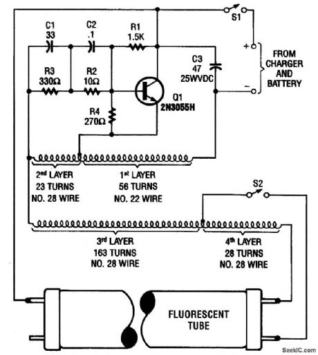
This high-voltage power supply can operate fluorescent tubes from a 12-V source, even if the tube has a defective filament. It essentially is an oscillator that excites a home-made autotransformer. T1 is wound on a ferrite rod 5/16 diameter by 1 7/8 long, in layers. S2 is an optional lamp filament switch. (View)
View full Circuit Diagram | Comments | Reading(980)
8_BIT_A_D_CONVERTER
Published:2009/6/24 1:33:00 Author:Jessie
View full Circuit Diagram | Comments | Reading(1163)
ELECTRONIC_METRONOME
Published:2009/6/23 22:56:00 Author:Jessie
RA sets the rate while R, sets the volume of clocks in the speaker. The 555 is configured as a low frequency oscillator. The circuit is powered 2N3904 by a 6 V battery. (View)
View full Circuit Diagram | Comments | Reading(1121)
Resistance(RC)Coupling Voltage Amplifier Circuit
Published:2011/7/12 3:26:00 Author:Michel | Keyword: Resistance, Coupling Voltage, Amplifier Circuit

The above picture is a typical diode or triode resistance amplifier circuit.Because of C1,C2 stopping direct current effect and each level DC work condition is complete independent,thus they can be modulated indepently.But, for ac signal, all levels have close relationship,the former stage output voltage is the latter stage input signal and total voltage amplification times of two levels amplifiers are equal to all level amplifiers product,namely,u=Au1*Au2.Meanwhile, the latter level input impedance is the former stage load. (View)
View full Circuit Diagram | Comments | Reading(2052)
Auto counter for producivity 1
Published:2011/7/29 2:41:00 Author:Ecco | Keyword: Auto counter , producivity

The auto counter for productivity described in the example uses infrared control technology, the circuit is simple and easy to make, the effect of on-site use is better, it can be used for automatic counting of a variety of assembly line production.
The working principle.
The auto counter for productivity circuit is composed of infrared transmitter and infrared receiver count circuit.
Infrared transmitter circuit is composed of a positive feedback modulation capacitor oscillator circuit, 4OkHz pulse oscillator and driver circuit, it is shown in Figure 8-80.
Positive feedback modulation capacitor oscillator circuit is composed of the NAND gate integrated circuit ICl (Dl-D4) internal Dl and D2 and resistors Rl and R2, capacitor Cl. 4OkHz pulse oscillator circuit is composed of the D3 and D4 inside of ICl and resistors R3 and R4, capacitor C2.
The drive circuit is composed of the IC and non-IC2 (D5, D6), resistors R5 and R6, transistor Vl and infrared light-emitting diode VLl.
Infrared receiver counting circuit is composed of the amplifier circuit, monostable trigger circuit A, B and counter, andit is shown in Figure 8-81.
The infrared receiver amplifier is composed of infrared receiver IC5, resistors R7 and R8 and the transistor V2.
A one-shot trigger circuit is composed of the time base IC lC3 and resistors R9 and Rll, capacitors C3-C5 and light-emitting diode VL2.
(View)
View full Circuit Diagram | Comments | Reading(686)
MUSICAL_INSTRUMENT_DIGITAL_INTERFACEMIDIRECEIVER
Published:2009/6/23 22:54:00 Author:Jessie
Receiver photodiode SFH250 is used to convert optical data pulses at 32.5 Kb to electrical signals. Buffer T2 feeds the signals to cascade amplifier T3-T4, then to op amp IC4, and buffers IC5-f and IC5-e. IC6 supplies 9 V for the circuit. (View)
View full Circuit Diagram | Comments | Reading(2372)
MULTIPLE_APERTURE_WINDOW_DISCRIMINATOR
Published:2009/6/23 5:07:00 Author:May

V1 through V4 are reference voltages that are derived from separate sources or from a com-mon voltage divider. (View)
View full Circuit Diagram | Comments | Reading(1)
PERFECT_PITCH
Published:2009/6/23 22:50:00 Author:Jessie

Perfect pitch, which is based on the 8751 H microprocessor, is an inexpensive and easy-to-build instrument tuner/frequency counter with a built-in headphone amplifier and a visual metronome. Perfect pitch converts the audio signal from your instrument to a digital signal, and displays the musical note you are playing and its frequency in real time on a 16-character liquid-crystal display. It also has an auxiliary audio input for radio, tape, or CD players so that you can tune up and play along with your favorite artists. (View)
View full Circuit Diagram | Comments | Reading(2129)
Auto counter for producivity 2
Published:2011/7/29 2:38:00 Author:Ecco | Keyword: Auto counter , producivity
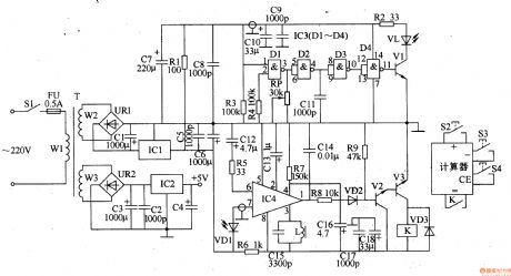
The auto counter for productivity described in the example uses infrared shading control circuit to accurately calculate the yield of the product.Itcan be used for beverages, beer and food packaging production line.
Power circuit is composed of the power switch Sl, fuse FU, power transformer T, rectifier bridge pile URl and UR2, three-terminal voltage regulator integrated circuit lCI and IC2, capacitors Cl-C8 and resistor R1.
Infrared transmitter circuit consists of NAND gate integrated circuit IC3 (Dl-D4), the transistor Vl, infrared light-emitting diode VL, resistors R2-R4, capacitors Cg-Cll and potentiometer RP.
Infrared receiver is composed of the infrared photodiode amplifier VDl, infrared signal processing integrated circuit IC4, resistors R5-R7, capacitors and inductors Cl2-Cl6 L. Control implementation circuit is composed of the resistors R8 and Rg, capacitors C17 and Cl8, diode VD2 and VD3, the transistor V2 and V3 and the relay K composition.
Count control circuit is composed of the fluorescent display calculators and thee normally open contact of K. (View)
View full Circuit Diagram | Comments | Reading(499)
| Pages:1358/2234 At 2013411342134313441345134613471348134913501351135213531354135513561357135813591360Under 20 |
Circuit Categories
power supply circuit
Amplifier Circuit
Basic Circuit
LED and Light Circuit
Sensor Circuit
Signal Processing
Electrical Equipment Circuit
Control Circuit
Remote Control Circuit
A/D-D/A Converter Circuit
Audio Circuit
Measuring and Test Circuit
Communication Circuit
Computer-Related Circuit
555 Circuit
Automotive Circuit
Repairing Circuit