Circuit Diagram
Index 1356
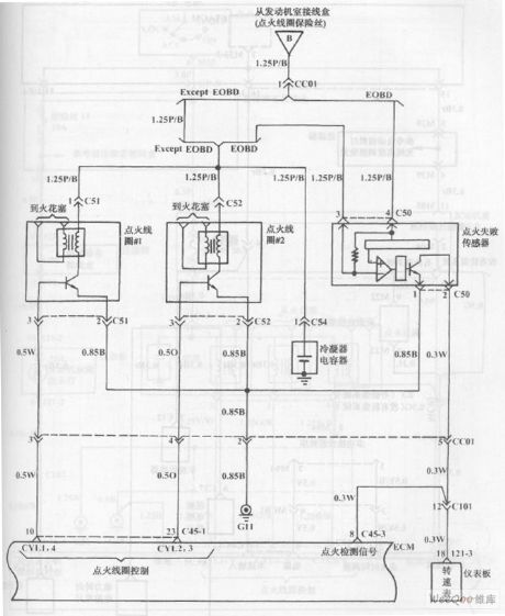
Fuel Injection System Circuit of Hyundai Sonata with 4-Cylinder Engine (8)
Published:2011/7/19 21:51:00 Author:Sue | Keyword: Fuel Injection, Hyundai Sonata, 4-Cylinder
The picture shows the fuel injection system circuit of Hyundai Sonata with 4-cylinder engine. (View)
View full Circuit Diagram | Comments | Reading(791)
HIGH_SPEED_3_BIT_A_D_CONVERTER
Published:2009/6/24 1:55:00 Author:May
View full Circuit Diagram | Comments | Reading(1116)
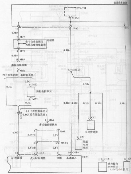
Fuel Injection System Circuit of Hyundai Sonata with 4-Cylinder Engine (7)
Published:2011/7/19 21:51:00 Author:Sue | Keyword: Fuel Injection, Hyundai Sonata, 4-Cylinder
The picture shows the fuel injection system circuit of Hyundai Sonata with 4-cylinder engine. (View)
View full Circuit Diagram | Comments | Reading(1166)
200_V_REGULATOR
Published:2009/6/24 1:55:00 Author:May

With high-voltage regulators, powering on the IC through the drive resistor for the pass transistors can become quite inefficient. This is avoided with the circuit shown. The supply current for the IC is derived from Q1. This allows R4 to be increased by an order of magnitude without affecting the dropout voltage.Selection of the output transistors will depend on voltage requirements. For output voltages above 200 V, it might be more economical to cascade lower-voltage transistors. (View)
View full Circuit Diagram | Comments | Reading(647)
Multivibrator Circuit Composed of Photocoupler
Published:2011/7/19 21:53:00 Author:Sue | Keyword: Multivibrator, Photocoupler

As seen in the figure 1, photocoupler composes the simplest multivibrator. After the power is on, as capacitor C's voltage can't change abruptly and resistor R's resistancevalue is larger than RL, so the power voltage Ec is mainly put on R. F's level is very low and LED is disconnected. As the capacitor's charging voltage is becoming larger and larger, F's level is becoming higher and higher. When it reaches a certain value, the LED will be connected and will be illuminated. The photistor will be connected. The output voltage will jump and become close to the power voltage. (View)
View full Circuit Diagram | Comments | Reading(465)
MUSICAL_INSTRUMENT_DIGITAL_INTERFACE(MIDI)TRANSMITTER
Published:2009/6/24 1:54:00 Author:May

Used for digital control of musical instruments, this transmitter converts the digital data signals to equivalent optical signals for fiberoptic cable interface. Optocoupler IC1 provides isolation, and drives IC2-a and -b and T1, and finally provides a cable driver LED (SFH750). (View)
View full Circuit Diagram | Comments | Reading(1730)
__HIGH_VOLTAGE_TRIPLEN
Published:2009/6/24 1:53:00 Author:May

This tripler is useful for low-current and high-voltage applications.The capacitors can be 0.001-μF,3- to 6-kV discs,and the diode's 3-kV units,or three each IN4007 in series. (View)
View full Circuit Diagram | Comments | Reading(726)
FAST_PRECISION_A_D_CONVERTER
Published:2009/6/24 1:53:00 Author:May
View full Circuit Diagram | Comments | Reading(725)
3_1_2_DIGIT_A_D_CONVERTER_WITH_LCD_DISPLAY
Published:2009/6/24 1:52:00 Author:May
View full Circuit Diagram | Comments | Reading(1151)
KIRLIAN_DEVICE_SUPPLY
Published:2009/6/24 1:50:00 Author:May
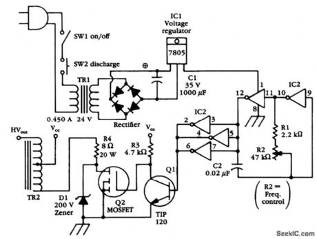
This device is essentially a high-voltage variable-frequency ac supply.A CD4049 IC multivibrator circuit drives a darlington connected transistor pair,which drives TR2,an HV transformer. (View)
View full Circuit Diagram | Comments | Reading(2046)
c8051f Simulator EC3
Published:2011/7/12 2:02:00 Author:Sue | Keyword: Simulator
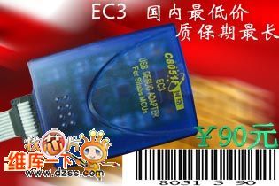
a) EC3 simulator is the latest series of MCU, and it uses the core technology of Silabs company.
b) It can realise functions as single step, hardware breakpoint, continuous single step, start and stop, modification and inspection of container and register, download of programs and encryption.
c) EC3 has the same functions as SILABS company's EC3.
It is the only domestic product that uses core technology of the origin company, so please recognize out signal C8015F Network . (View)
View full Circuit Diagram | Comments | Reading(420)
TRACKING_SERVO_TYPE_A_D_CONVERTER
Published:2009/6/24 1:48:00 Author:May
View full Circuit Diagram | Comments | Reading(789)
THREE_DECADE_LOGARITHMIC_A_D_CONVERTER
Published:2009/6/24 1:47:00 Author:May
View full Circuit Diagram | Comments | Reading(1061)
HV_REGULATOR_WITH_FOLDBACK_CURRENT_LIMIT
Published:2009/6/24 1:46:00 Author:May

The output current issensed across R8, This is delivered to the current-limit arrtplifier through R7, across which the foldback potential is developed by R6 with a threshold determined by D4. The values given limit the peak power below 20 W and shut off the pass transistors when the voltage across them exceeds 310 V. With unregulated input voltages above this value, start-up is initiated solely by the current through R5. Q4 is added to provide some control on current before A2 has time to react.The circuit is stable with an output capacitor greater than about 2 μF. Spurious oscillations in current limit are suppressed by C2 and R4, while a strange, latch-mode oscillation coming out of current limit is killed with C1 and R1. (View)
View full Circuit Diagram | Comments | Reading(1135)
FOUR_CHANNEL_DIGITALLY_MULTIPLEXED_RAMP_A_D_CONVERTER
Published:2009/6/24 1:43:00 Author:May
View full Circuit Diagram | Comments | Reading(743)
ac_OPERATED_HE_NE_POWER_SUPPLY
Published:2009/6/24 1:43:00 Author:May
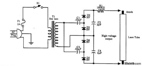
T1 is a 120-V to 1000-V step-up 60-Hz transformer. C1, C2, C3, C4 and D2 through D5 form a voltage quadruplet. The initial voltage is 4 to 5 kV, which drops when the laser tube fires. (View)
View full Circuit Diagram | Comments | Reading(523)
8_BIT_SUCCESSIVE_APPROXIMATION_A_D_CONVERTER
Published:2009/6/24 1:42:00 Author:May
View full Circuit Diagram | Comments | Reading(1)
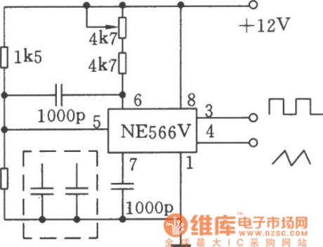
using NE566V for composing 20kHz waveform generator circuit
Published:2011/7/23 9:27:00 Author:John | Keyword: waveform generator
View full Circuit Diagram | Comments | Reading(523)
Single precision function generator ICL8038 application circuit
Published:2011/7/23 9:27:00 Author:John | Keyword: Single precision function generator, application circuit
View full Circuit Diagram | Comments | Reading(4822)
Precise second-pulse signal generator circuit
Published:2011/7/23 9:28:00 Author:John | Keyword: second-pulse signal generator
View full Circuit Diagram | Comments | Reading(481)
| Pages:1356/2234 At 2013411342134313441345134613471348134913501351135213531354135513561357135813591360Under 20 |
Circuit Categories
power supply circuit
Amplifier Circuit
Basic Circuit
LED and Light Circuit
Sensor Circuit
Signal Processing
Electrical Equipment Circuit
Control Circuit
Remote Control Circuit
A/D-D/A Converter Circuit
Audio Circuit
Measuring and Test Circuit
Communication Circuit
Computer-Related Circuit
555 Circuit
Automotive Circuit
Repairing Circuit


