
Circuit Diagram
Index 1352
SHARP_SQUARE_WAVEFORMS_FROM_MULTIVIBRATOR
Published:2009/6/24 2:50:00 Author:Jessie

By using diodes as shown, the loading effect on the collector of the transistors caused by the tim-irtg capacitors can be avoided. As the collector of the transistors rises toward VCC the diode discon-nects the tinting capacitors. (View)
View full Circuit Diagram | Comments | Reading(1106)
SQUARE_WAVE_GENERATOR
Published:2009/6/24 2:50:00 Author:Jessie

A 60-Hz waveform from T1 drives an audio amplifier to clipping. Output is 60 Hz with about 0- to 1.4-V p-p amplitude. (View)
View full Circuit Diagram | Comments | Reading(0)
ADJUSTABLE_0_TO_5_V_SUPPLY
Published:2009/6/24 2:50:00 Author:Jessie

Although linear-regulator ICs are frequently used In variable p。wer-supply applications,they might not always be the best choice,At low output voltages,power losses in these regulators cancause headaches for designers For example,if an output current of 1.25 A is required at 1.25 V from an input of 8 V.a regulator (such as the LT317)dissipates more than 10 W.The figure depicts a dc-dc converter that functionally replaces a linear regulator in the just clescribed application. The converter not only-eliminates the problem of power loss,but it can be adjusted for output voltages (as low as 25 mV)while delivering an output current of 1.5 A.The circuit uses a basic positive-buck topology with one exception,A control voltage is applied through R4 to the feedback summing node at pin of the LT1076 regulator IC,making it possible to adjust the output from0 V to approximately 6 V. This range encompasses the 3.3-V and 5-V logic supplyvoltages for portable and desktop equipment,as well as battery-pack combinations of one to four cells.As R4is driven from0 to 5 V by the buffer (U1),more or less current is required from R2 to satisfy the loop’s desire to hold the feedback summing point at 2.37V. This forces the converter’s out-put to swlng over the range of0 to 6 V.The LT1076 is capable of 1.75-A guaranteed output current In this application,and 2 A is typical.If more current is required,the LT1074 can be substituted for the LT1076. (View)
View full Circuit Diagram | Comments | Reading(1572)
SIMPLE_NOISE_LIMITER_FOR_RECEIVERS
Published:2009/6/24 2:48:00 Author:Jessie
This circuit uses a diode series clipper to limit noise peaks on a received signal. It is best used, where several volts p-p of audio signal are available. (View)
View full Circuit Diagram | Comments | Reading(594)
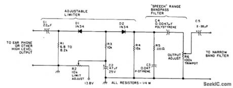
RECEIVER_AF_NOISE_LIMITER_FOR_LOW_LEVEL_SIGNALS
Published:2009/6/24 2:46:00 Author:Jessie

A preamplifier in the audio frequency range amplifies a noisy audio signal to drive a diode clip-per. Suitable audio input levels would be in the 10-mV to 1-V range. (View)
View full Circuit Diagram | Comments | Reading(1209)
GUNSHOT_SOUND_EFFECTS_GENERATOR
Published:2009/6/24 2:46:00 Author:Jessie

Gunshot sound-effects generator built around a Texas Instruments SN76477 sound chip. An in-put pulse causes IC1 to generate a gunshot sound. (View)
View full Circuit Diagram | Comments | Reading(3292)
FEEDBACK_OSCILIATOR
Published:2009/6/24 2:40:00 Author:May

Circuit oscillates because the transistor shifts the phase of the signal 180° from the base to the collector. Each of the RC networks in the circuit is designed to shift the phase 60°at the frequency of oscillation for a total of 180°. The appropriate values of R and C for each network is found from f = 1/2√3πRC); that equation allows for the 60°phase shift required by the design. (View)
View full Circuit Diagram | Comments | Reading(699)
800_Hz_OSCILLATOR
Published:2009/6/24 2:46:00 Author:Jessie

The following transistors may be used: HEP-254, O.C-2, SK-3004, AT30H. To increase the frequency, decrease the value of the capacitors in the ladder network. (View)
View full Circuit Diagram | Comments | Reading(1306)
DUAL_TONE_GENERATOR
Published:2009/6/24 2:39:00 Author:May
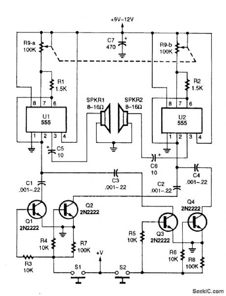
Two 555 oscillator/timers are configured similarly as audio oscillators, with each oscillator feeding a separate speaker.A dual 100-kQ potentiometer is use to tune the two oscillators simultaneously. The oscillators' frequency range is controlled by a dual-transistor switch, which selects the timing capacitor for both oscillators. Although the circuit only shows two range-switching circuits, any number can be added by simply duplicating the two-transistor switching circuit. (View)
View full Circuit Diagram | Comments | Reading(717)
±15_V_POWER_SUPPLY
Published:2009/6/24 2:39:00 Author:May

A simple bridge rectifier feeds two IC regulators. This circuit should be useful for op-amp circuitry. (View)
View full Circuit Diagram | Comments | Reading(2380)
PRECISE_dc_MOTOR_SPEED_CONTROLLER
Published:2009/6/24 2:39:00 Author:May
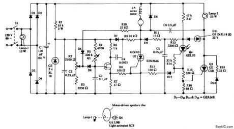
A series dc motor can be made to have the same characteristics as an ac synchronous motor using this circuit. This control technique is useful where a constant motor speed is needed. (View)
View full Circuit Diagram | Comments | Reading(2386)
ELECTRONIC_WIND_CHIME
Published:2009/6/24 2:45:00 Author:Jessie

The value of R4 controls the damping or decay time of the feedback circuit (a twin Tee oscillator). When S1 is closed, the circuit breaks into oscillation. When S1 is opened, the circuit stops oscillating generating a decaying tone like a bell.The frequency is approximately 1/2 RC. C1, C2, and C3 are typically in the 0.01-μF range. (View)
View full Circuit Diagram | Comments | Reading(1469)
GENERAL_PURPOSE_POWER_SUPPLY_FOR_AUTOMOTIVE_PROJECTS
Published:2009/6/24 2:38:00 Author:May

This supply produces 12 V and 5 V for a variety of automotive projects. F4 is connected directly to the alternator field winding (usable only if your car has a separate regulator). (View)
View full Circuit Diagram | Comments | Reading(560)
PHASE_SHIFT_OSCILLATOR
Published:2009/6/24 2:45:00 Author:Jessie

A single transistor makes a simple phase shift oscillator. The output is a sine wave with distortion of about 104. The sine wave purity can be increased by putting a variable resistor (25 ohms) in the emitter lead of Q1 (x). The resistor is adjusted so the circuit is only just oscillating, then the sine wave is relatively pure. Operating frequency may be varied by putting a 10 K variable resistor In serles with R3,Or by changing C1,C2,and C3.Making C1,2, 3 equal to 100 nF will halve the operatingfrequency,Operating frequencycanalso bevoltage controlled by a FET In serles with R3,Or optically controlled by an LDR In serles with R3. (View)
View full Circuit Diagram | Comments | Reading(0)
COMPLEX_SOUND_EFFECT_GENERATOR
Published:2009/6/24 2:38:00 Author:May
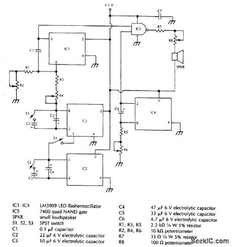
This system uses four free running oscillators to produce a wide variety of complex sounds. LF oscillator IC3 modulates IC2, which modulates IC1. The audio from IC1 is combined with a variable frequency from IC4. Switches at various points allow oscillators IC3 to be switched in or out, IC1 and IC2 to be varied in frequency, and IC4 also can be varied in frequency. The circuit is not critical and different arrangements can be tried to produce various sound effects. (View)
View full Circuit Diagram | Comments | Reading(1408)
ROBOTIC_CHATTER_SOUND_GENERATOR
Published:2009/6/24 2:44:00 Author:Jessie


This circuit simulates sound effects of a robot, for toy or novelty applications.
(View)
View full Circuit Diagram | Comments | Reading(0)
Automatic Sprinkling Irrigation Controller (7)
Published:2011/7/14 5:56:00 Author:Sue | Keyword: Automatic, Sprinkling Irrigation, Controller

When the soil humidity is proper, the resistance value between the humidity detector's two probes is small. D1's input terminal has low level and the schmitt trigger cannot be triggered. Then D4 outputs high level which will make V1 and V2 disconnected. K is not connected and the water pump doesn't work. VL2 is not illuminated. At the same time, V3 is connected, VL1 is illuminated which indicates that the soil humidity is proper.
When the soil humidity is low enough, and the resistance value between the humidity sensor's two probes reaches a certain given value, the schmitt trigger will be reversed. The monostable trigger will get a negative skipping pulse through C2 which will make the monostable trigger reversed. D4 will output low level which will make V3 disconnected. VL1 is illuminated. V1 and V2 are connected and K is connected. The water pump begins to work. At the same time VL2 will be illuminated indicating that it is sprinkling. (View)
View full Circuit Diagram | Comments | Reading(615)
TONE_ENCODER
Published:2009/6/24 2:35:00 Author:May

A basic twin-T circuit uses resistors for accurately setting the frequency of theoutput tones, selected by pushbutton. Momentary switches produce a tone only when the button is depressed. (View)
View full Circuit Diagram | Comments | Reading(0)
PHASE_SHIFT_OSCILLATOR
Published:2009/6/24 2:33:00 Author:May

ircuit uses a simple RC network to pro-duce an exceptionally shrill tone from a minia-ture speaker. With the parts values shown, the circuit oscillates at a frequency of 3.6 kHz and drives a miniature 2 1/2 speaker with ear-piercing volume. The output waveform is a square wave with a width of 150 pts, sloping rise and fall times, and a peak-to-peak amplitude of 4.2 volts (when powered by 9 volts). Current drain of the oscillator is 90 mA at 9 volts, and total power dissipation at this voltage is 0.81 watt, which is well below the 1.25 watts the 14-pin version will absorb (at room temperature) before shutting down. (View)
View full Circuit Diagram | Comments | Reading(0)
SIMPLE_CODE_PRACTICE_OSCILLATOR
Published:2009/6/24 2:33:00 Author:May

With only a minor circuit change, the basic LM3909 oscillator configuration can be turned into a code-practice oscillator. (View)
View full Circuit Diagram | Comments | Reading(0)
| Pages:1352/2234 At 2013411342134313441345134613471348134913501351135213531354135513561357135813591360Under 20 |
Circuit Categories
power supply circuit
Amplifier Circuit
Basic Circuit
LED and Light Circuit
Sensor Circuit
Signal Processing
Electrical Equipment Circuit
Control Circuit
Remote Control Circuit
A/D-D/A Converter Circuit
Audio Circuit
Measuring and Test Circuit
Communication Circuit
Computer-Related Circuit
555 Circuit
Automotive Circuit
Repairing Circuit