Control Circuit
Division Circuit Composed of NE555
Published:2011/7/27 5:38:00 Author:Sue | Keyword: Division Circuit | From:SeekIC

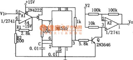
The picture shows the division circuit composed of voltage-frequency converter and amplitude modulator. The input voltage V1 controls field effect tube 2N4222's inner resistance value through operational amplifier A1, so the oscillate frequency of the nonstable multivibrator will be changed.A2 is the amplitude modulator. After the input signal V2 is modulated, it will be output. Presume field effect tube's pinch-off voltage is Vp. If Vp=(1+R1/R2), then the relation between input and output is : Vo=-V2/V1. V1 and V2 are required to have a range of 0-10V. The output Vo is an average value which can be obtained through the filter. It can also be obtained by reading the damped voltmeter.
Reprinted Url Of This Article:
http://www.seekic.com/circuit_diagram/Control_Circuit/Division_Circuit_Composed_of_NE555.html
Print this Page | Comments | Reading(3)

Article Categories
power supply circuit
Amplifier Circuit
Basic Circuit
LED and Light Circuit
Sensor Circuit
Signal Processing
Electrical Equipment Circuit
Control Circuit
Remote Control Circuit
A/D-D/A Converter Circuit
Audio Circuit
Measuring and Test Circuit
Communication Circuit
Computer-Related Circuit
555 Circuit
Automotive Circuit
Repairing Circuit
Code: