
Circuit Diagram
Index 1068
1_2_kHz_TONE_GENERATOR
Published:2009/7/6 0:35:00 Author:May
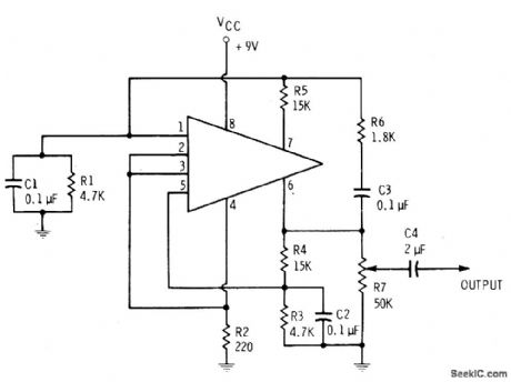
Simple feedback circuit converts HEP 580 IC to emitter-coupled MVBR producing reasonably sinusoidal output somewhere between 1 and 2 kHz. Supply is 9-V battery.-E. M. Noll, Linear IC Principles, Experiments, and Projects, Howard W. Sams, Indianapolis, IN, 1974, p 64-65. (View)
View full Circuit Diagram | Comments | Reading(1072)
150_500_kHz_CRYSTAL
Published:2009/7/6 0:35:00 Author:May

Circuit is series-mode if C1 is 0.01 μF. Parallel-mode crystals can be used if C1 is equal to specified load capacitance (30, 50, or 100 pF) for crystal. Harmonic output is usually better than -30 dB. Circuit is particularly good for crystals prone to oscillate undesirably at twice fundamental frequency. L1 is 800-2000 μH for 150-300 kHz, and 360-1000 μH for 300-500 kHz. Adjusting slug in L1 pulls crystal frequency. Q1 is 2N3563, 2N3564, 2N3693, BC107, BC547, or SE1010.-R. Harrison, Survey of Crystal Oscillators, Ham Radio, March 1976, p 10-22. (View)
View full Circuit Diagram | Comments | Reading(886)
CURRENT_TUNED_UHF_TUNER
Published:2009/7/23 21:47:00 Author:Jessie
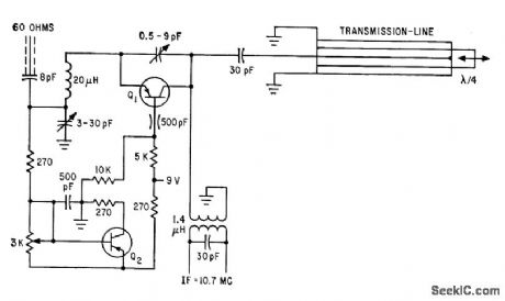
Circuit permits operation of transistors beyond rated frequency limit. Transistor is used as negative-feedback oscillator whose frequency is determined by length of coaxial line. Operation is similar to that of parametric amplifier.-U. L. Rohde, Pushing Transistors Above Their Frequency Limits, Electronics, 35:25, p 46-49. (View)
View full Circuit Diagram | Comments | Reading(581)
4_MHz_COUNTER
Published:2009/7/5 23:59:00 Author:May

Portable frequency counter using RCA CMOS logic draws only 300 mW (12 V at 25 mA) yet operates to well above 4 MHz.Supply voltage can be between 4 and 15 V, loosely regulated, without affecting accuracy.Display uses multiplexing with 10% duty cycle to minimize battery drain. One multiplexed output is for three least signmcint figures and other for four most significant figures. Article describes operation in detail. Applications in.dude setting RTTY mark and space tones, FM repeatertones, signal-generator frequencies for TV alignment, tuning musical instruments, and serving as tachometer or speedometer in car.-R. M. Mendelson, Milliwatt Portable Counter, Ham Fladio, Feb. 1977, p 22-25.
(View)
View full Circuit Diagram | Comments | Reading(1705)
WlEN_BRIDGE_2_W
Published:2009/7/5 23:57:00 Author:May
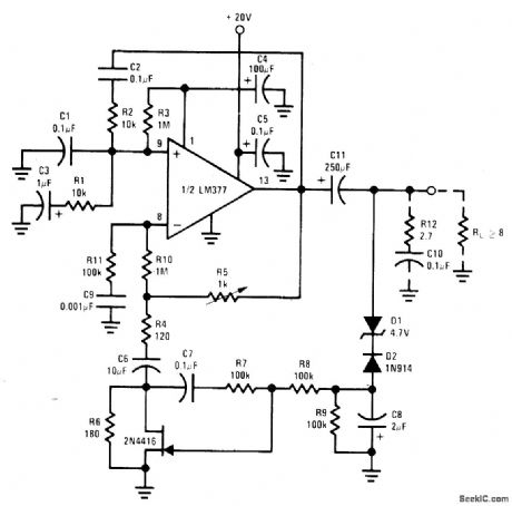
Uses haff of LM377 IC connected as oscillator, with FET amplitude stabiIization in negative feedback path. Total harmonic distortion is under 1% up to 10 kHz. With values shown, maximum output is 5.3 VRMS at 60 Hz. R12 and C10 are added if necessary to prevent high-frequency instability.- Audio Handbook, National Semiconductor. Santa Clara. CA. 1977. p 4.8-4-20. (View)
View full Circuit Diagram | Comments | Reading(591)
AUTO_BREAKDOWN_FLASHER
Published:2009/7/5 23:55:00 Author:May

Two-transistor amplifer with regenerative feedback sends 60-ms pulses of currents up to several amperes through low-voltage lamp to give high-brilliance flashes without destroying lamp. L1 can be PR-2 lamp (Radio Shack 272-1120).-F. M.Mims, Transistor Projects, Vol. 1, Radio Shack, Fort Worth, LX, 1977, 2nd Ed., p 27-32.
(View)
View full Circuit Diagram | Comments | Reading(700)
STEPPER_MOTOR_TESTER
Published:2009/7/23 21:47:00 Author:Jessie
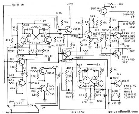
Digital test equipment automatically evaluates performance of magnetically detented stepper motors in several modes, for wide variety of test conditions. Analyzer compares number of applied voltage steps with number of motor movements. Pulse train from power amplifier is gated through logic circuits that pre vent switching from occurring in middle of pulse, and keep input pulse line closed even when switching motor direction.-H. J. Weber and M. Weiss, Analyzing Magnetically-De-tented Stepper Servo Motors, Electronics, 33:39, p 71-74. (View)
View full Circuit Diagram | Comments | Reading(922)
FERRITE_CUP_TUNER
Published:2009/7/23 21:46:00 Author:Jessie
Rotary-axial tuner consists of two pairs of ferrite cups with ground D-shaped center cores, ganged to produce linear frequency variation from 500 to 1,600 kc with 270℃ rotation, Operating frequencies can be extended to 15 Mc.-E. A. Abbot and M. Lafer, Miniature Ferrite Tuner Covers Broadcast Band, Electronics, 31;9, p 72-73. (View)
View full Circuit Diagram | Comments | Reading(657)
TV_STATION_CONTROL
Published:2009/7/23 21:46:00 Author:Jessie
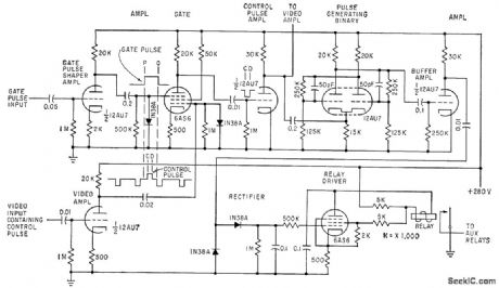
Control pulses transmitted in blanking interval by tv network transmitter are decoded by receiver circuits shown and translated into six different switching actions used to introduce special program matter such as commercials, weather reports, and local film projector material that may be different for each network station.-K. Kazama and T. Ishino, Remote Tv Control by Blanking-Interval Pulses, Electronics, 33:20, p 79-81. (View)
View full Circuit Diagram | Comments | Reading(1502)
Reset Timing Circuit of Power Supply Connection
Published:2011/7/25 23:39:00 Author:Michel | Keyword: Power Supply, Reset Timing Circuit

Picture 1 is reset circuit of power supply connection.The function of NE555 feet 4 is that it works when it is connected to high PWL and it resets when it is connected to low PWL.R3 and C2 are connected to feet 4,this circuit has time constant functions. Therefore, the power supply is connected,feet 4 won't rise to + Ucc immediately,which needs R3 and C2 constant delay.In this period, even if feet 2 inputs pulse, feet 3 trigger output still remains low level.R2 and R4 are ME555 current limiting resistance and TTL level triggering pulse triggers NE555 feet 2 directly via R2.VD1 is the diode which makes C2 discharge fast when the power supply is off and it outputs pulse width T=R5C4. (View)
View full Circuit Diagram | Comments | Reading(641)
SWITCHING_DIODE_TESTER
Published:2009/7/23 21:46:00 Author:Jessie

Used in checking performance of computer diodes when handling steep-edged, short-duration pulses. Negative input pulse cuts off diode current, and sampling oscilloscope with 1,000-Mc band-width permits study of diode recovery limes down to 500 picosec.-W. S. Eckess and P. G. Docket, Measurement of Diode Switching Characteristics, Electronics, 33:15, p 59-61. (View)
View full Circuit Diagram | Comments | Reading(710)
8_bit_D_A_converter_with_microprocessor_interface_1
Published:2009/7/23 21:46:00 Author:Jessie

This circuit uses a DAC-4888 and a few external components to form a D/A converter with microprocessor interface (8-bit data bus). The output is 0 to -4 mA with straight binary input and an external reference. (View)
View full Circuit Diagram | Comments | Reading(870)
electronic sterilizer circuit diagram
Published:2011/7/13 9:36:00 Author:Nancy | Keyword: electrpnic sterilizer
View full Circuit Diagram | Comments | Reading(2138)
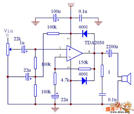
TDA2030 power amplifier circuit double power connecting method circuit diagram
Published:2011/7/13 9:36:00 Author:Nancy | Keyword: power amplifier, double power, connecting method

The power rating of TDA2030 power amplifier circuit double power connecting method is 14W. The power supply voltage is + 6 ~ + 18 V. Output current is big, harmonic distortion and crossover distortion is small (+ 14 V/4 ohms, THD = 0.5%). (View)
View full Circuit Diagram | Comments | Reading(3194)
Differential_input_instrumentation_amplifier
Published:2009/7/23 21:45:00 Author:Jessie


This circuit uses three sections of a 4136 to form an instrumentation amplifier, where the common-mode rejection ratio depends on the matching of resistors. (View)
View full Circuit Diagram | Comments | Reading(1360)
AM_IF_and_detector_with_noise_blanker
Published:2009/7/23 21:45:00 Author:Jessie
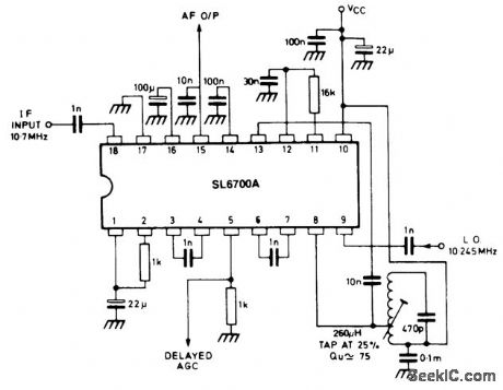
The SL6700 shown is similar to the SL6701 (Fig. 2-12), but with the addition of a noise blanker. The circuit shown in Fig. 2-13 is for an AM double-conv ersion receiver with noise blanker. (View)
View full Circuit Diagram | Comments | Reading(2234)
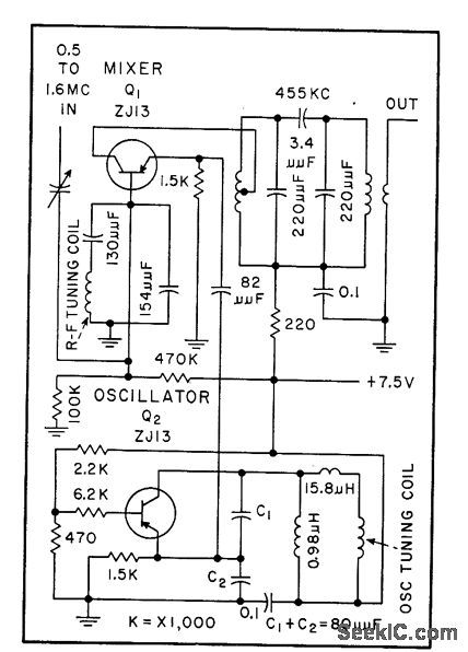
PANORAMIC_FRONT_END
Published:2009/7/23 21:45:00 Author:Jessie
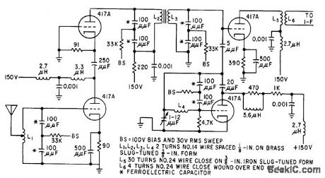
Can be made as three plug-in units, each containing the electrically tunable r-f, mixer, and local oscillator stages to cover 35 to 70, 70 to 130, and 130 to 200 Mc. Each plug-in front end has eight voltage-tunable ferroelectric tuners.-T. W. Butler, Jr., Ferroelectrics Tune Electronic Circuits, Electronics, 32:3, p 52-55. (View)
View full Circuit Diagram | Comments | Reading(424)
TDA2030 power amplifier circuit single power connecting method circuit diagram
Published:2011/7/13 9:37:00 Author:Nancy | Keyword: power amplifier, single power, connecting method,
The power rating of TDA2030 power amplifier circuit double power connecting method is 14W. The power supply voltage is + 6 ~ + 18 V. Output current is big, harmonic distortion and crossover distortion is small (+ 14 V/4 ohms, THD = 0.5%). (View)
View full Circuit Diagram | Comments | Reading(1787)
27255_MC_REMOTE_CONTROL_RECEIVER
Published:2009/7/23 21:45:00 Author:Jessie

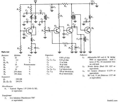
Output of superregenerative detector consists of 200-kc quench signal and 1,000-cps tone modulation from incoming signal. Quench fiber passes only audio signal to amplifier.Amplified audio is detected and resulting direct current used to operate relay K1.-Texcts Instruments Inc., Transistor Circuit Design, McGraw-Hill, N.Y., 1963, p 363. (View)
View full Circuit Diagram | Comments | Reading(1997)
High_impedance_differential_amplifier
Published:2009/7/23 21:44:00 Author:Jessie

This circuit uses three sections of a 3404 op amp to form a high-impedance amplifier, where the output depends on the difference between V1 and V2, as well as the resistance ratios. By eliminating the input resistances (such as shown in Fig. 10-29), input impedance depends on the 3404 alone.
(View)
View full Circuit Diagram | Comments | Reading(0)
| Pages:1068/2234 At 2010611062106310641065106610671068106910701071107210731074107510761077107810791080Under 20 |
Circuit Categories
power supply circuit
Amplifier Circuit
Basic Circuit
LED and Light Circuit
Sensor Circuit
Signal Processing
Electrical Equipment Circuit
Control Circuit
Remote Control Circuit
A/D-D/A Converter Circuit
Audio Circuit
Measuring and Test Circuit
Communication Circuit
Computer-Related Circuit
555 Circuit
Automotive Circuit
Repairing Circuit