
Circuit Diagram
Index 1062
PRECISION_ENVELOPE_DETECTOR
Published:2009/7/6 2:02:00 Author:May


This circuit is useful for signal-processing sonar data recorded on an instrumentation-quality analog tape recorder. The envelope detector utilizes ready available parts, and furnishes accuracy beyond 100 kHz. Two LM301 op amps connected as precision absolute-value circuits use 2-pole frequency compensa-tion for increased slew rate. And one section of an LM324 quad op amp connected in a Butterworth LPF configuration subjects the rectifier's output to a low-pass filter. (View)
View full Circuit Diagram | Comments | Reading(2188)
RAMP_GENERATOR
Published:2009/7/6 2:01:00 Author:May

Circuit Notes
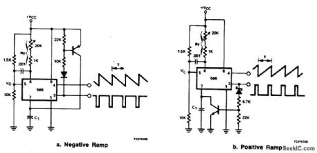
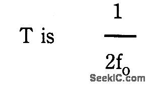
The 566 can be wired as a positive or negative ramp generator. In the positive ramp generator, the external transistor driven by the Pin 3 output rapidly discharges C1 at the end of the charging period so that charging can resume instantaneously. The pnp transistor of the negative ramp generator likewise rapidly charges the timing capacitor C1 at the end of the discharge period. Because the circuits are reset so quickly, the temperature stability of the ramp generator is excellent. The period
where fo is the 566 free-running frequency in normal operation. Therefore,where VC is the bias voltage at Pin 5 and RT is the total resistance between Pin 6 and VCC. Note that a short pulse is available at Pin 3. (Placing collector resistance in series with the external transistor collector will lengthen the pulse.) (View)
View full Circuit Diagram | Comments | Reading(2)
16_bit_D_A_converter_with_microprocessor_interface
Published:2009/7/23 21:40:00 Author:Jessie

This circuit uses a DAC-4881 and a few external components to form a D/A converter with microprocessor interface (16-bit data bus). The output is 0 to -4 mA with straight binary input and an external reference. (View)
View full Circuit Diagram | Comments | Reading(626)
200_MHz_BUFFER
Published:2009/7/6 2:01:00 Author:May
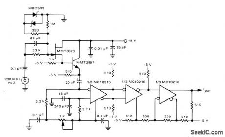
Developed for use ahead of prescaler in 200-MHz auto ranging frequency counter. Provides high input impedance to count-sensing device. Circuit includes Schmitt trigger action. Sensitivity is about 50 mV P-P.-T. Balph, A 200 MHz Autoranging MECL-McMOS Frequency Counter, Motorola, Phoenix, AZ, 1975, AN-742,p 10. (View)
View full Circuit Diagram | Comments | Reading(3133)
XR2240_XYNTHESIZER_
Published:2009/7/6 2:01:00 Author:May
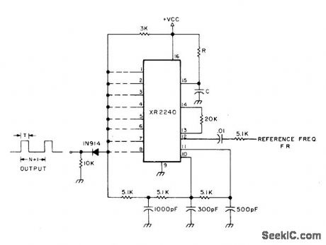
Circuit uses XR2240 programmable timer/counter for simultaneous multiplication of input frequency FR by factor of M and division of input frequency by factor of N + 1, where M and N are integers selected by appropriate connections of binary pins 1-8 to common output bus. Output frequency is then FR(M)/(1 + N) where M is between 1 and 10 inclusive and N is between 1 and 255 inclusive.VCC is 4-15 V.-H. M. Berlin, IC Timer Review, 73 Magazine, Jan. 1978, p 40-45. (View)
View full Circuit Diagram | Comments | Reading(1482)
REMOTE_CONTROL_OF_AMPLIFIER_GAIN
Published:2009/7/23 21:40:00 Author:Jessie

Permits control of gain of small signal amplifier by means of d-c voltage. Adjustment potentiometer does not carry signal cur rent. D-c control voltage acts on 6-v zener diode which in turn controls amplifier gain. Control voltage is limited to -4 v, which makes gain adjustable between 0.04 and 0.7 for range of 1 to 18. Input signal is 1 V pp sine wave.-T. Molligna, Amplifier with DC Controlled Gain, EEE, 11:5, p 94-96. (View)
View full Circuit Diagram | Comments | Reading(994)
TWO_DECADE_SCALER
Published:2009/7/6 1:59:00 Author:May
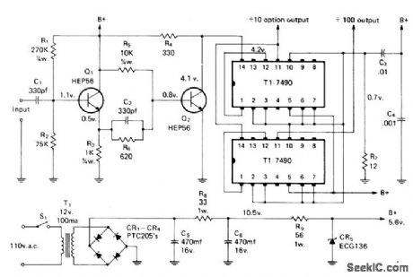
Solid-state frequency scaler extends range of older frequency counters by factors of 10 and 100, or up to 10 MHz for 100-kHz counter. Emitter-follower Q1 provides matching from high input impedance to low impedance for driving sensitive clipper Q2 that operates class B and presents 4 V P-P square wave to decade counter. Input accepts 1 to 14 V P-P.-D. Peck, A Solid State Scaler for Frequency Counters, CQ, April 1974, p 24-27.
(View)
View full Circuit Diagram | Comments | Reading(853)
AUDIO_DECIBEL_LEVEL_DETECTOR_WITH_METER_DRIVER
Published:2009/7/6 1:58:00 Author:May

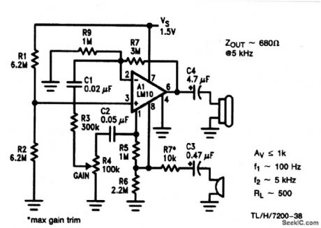
This circuit draws very little power, less than 5 mA with a single 6-V power supply, making it ideal for portable battery-operated equipment. The small size and low power consumption belie the 90-dB dynamic range and 10.5-μV sensitivity. Dc output voltage proportional to the log10 of the input signal level. Thus, a standard 0-5 voltmeter can be linearly calibrated in decibels over a single 80-dB range. The circuit is within 1.5-dB tolerance over the 80-dB range for audio frequencies from 100 Hz to 10 kHz. Higher audio levels can be measured by placing an attenuator ahead of the input capacitor. (View)
View full Circuit Diagram | Comments | Reading(1343)
Simple_voltage_reference
Published:2009/7/23 21:40:00 Author:Jessie
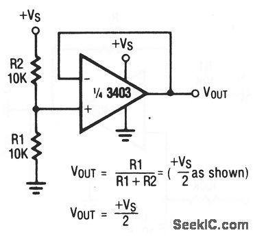
This circuit uses one section of a 3403 op amp as a voltage reference.Compare this basic circuit to the higher-precision circuit of Fig. (View)
View full Circuit Diagram | Comments | Reading(600)
Difference_amplifier
Published:2009/7/23 21:39:00 Author:Jessie
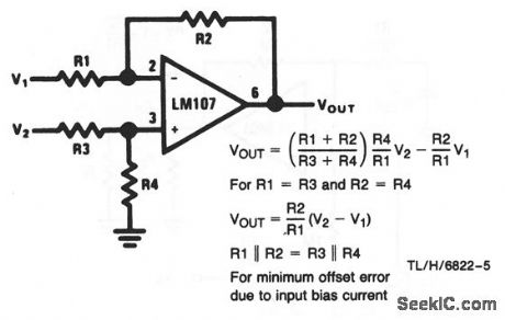
This circuit shows an LM107 that is connected in the classic difference-amplifier configuration, where VOUT depends on the difference between V1 and V2 as well as the ratios of R1 through R4. As shown, the calculations for VOUT are simplified when R1=R3 and R2= R4. (View)
View full Circuit Diagram | Comments | Reading(0)
15_GHz_PRESCALER
Published:2009/7/6 1:55:00 Author:May
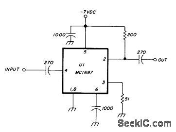
Motorola MC1697 IC provides division by 4 to extend operating range of 400-MHz counter above 1.5 GHz. Circuit will operate on input signals as low as 1 mW. Requires 60-mA power supply at -7 V.Article gives construction and test details.-J.Hinshaw, 1.5 GHz Divide-by-Four Presealer, Ham Radio, Dec, 1978, p 84-86. (View)
View full Circuit Diagram | Comments | Reading(746)
WIDEBAND_F_M_RADIO_CONTROL_LINK
Published:2009/7/23 21:39:00 Author:Jessie
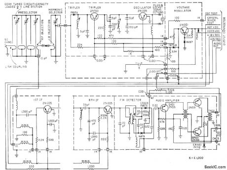
Covers 406 to 549 Mc. Used in missiles and missile-target aircraft to receive up to 20 tone channels and provide demodulated audio output to decoding equipment. Second through seventh i-f channels are essentially same as eighth.-T. L. Fischer, Wideband F.M Receiver for Remote Aircraft Control, Electronics, 33:40, p 85-87. (View)
View full Circuit Diagram | Comments | Reading(1690)
6_MHz_WITH_10_Hz_RESOLUTION
Published:2009/7/6 1:54:00 Author:May
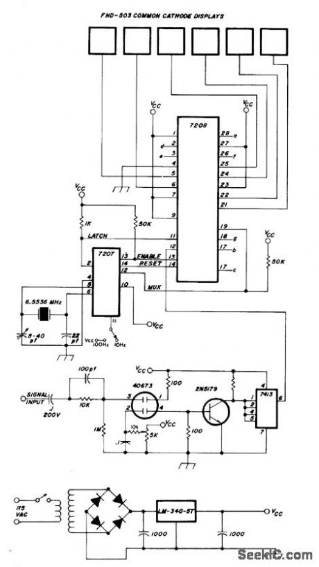
Intersil 7208 CMOS counter provides multiplexing of six digits in Fairchild display operating from 5-V regulated supply. Uses MOSFET 4673 input stage,-H, E. Harris, Simplifying the Digital Frequency Counter, Ham Radio, Feb, 1978, p 22-25. (View)
View full Circuit Diagram | Comments | Reading(666)
RADAR_SIGNAL_DETECTOR
Published:2009/7/6 1:54:00 Author:May

Circuit Notes
The circuit can be tuned to respond to signals between 50 MHz and 500 GHz. The economy model is shown in Fig. 1, and the deluxe model is shown in Fig. 2. The ftrst op amp in each circuit functions as a culrent-to-voltage converter. In the economy model IC1b buffers the output to drive the piezo buzzer. The deluxe model functions in a similar manner except that IC1b is configured as a x20 buffer amplifier to drive the LM386. In both circuits C1 functions as a transmission line that intercepts the incident radar signal. The response may be optimized by trimming C1's lead length for the desired frequency. Typically the capacitor's leads should be 0.5-0.6 inches long. (View)
View full Circuit Diagram | Comments | Reading(1291)
PORTABLE_TV_TUNER
Published:2009/7/23 21:39:00 Author:Jessie
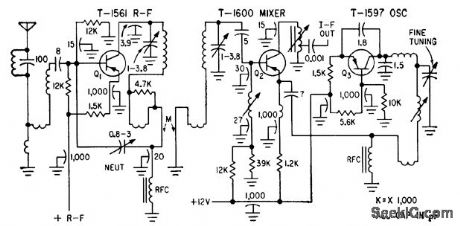
Three transistors in vhf tuner provide 19 db power gain even for channel 13, with 12 db noise factor. V. Mukai and P. V. Simpson, Transistorized Tuners For Portable Television, Electronics, 33:12, p 76-78. (View)
View full Circuit Diagram | Comments | Reading(2289)
DIRECT_COUPLED_PREAMP
Published:2009/7/6 1:52:00 Author:May

Provldes frequency response from 0 to 1 MHz at very low power levels, as required fordriving CMOS logic of frequency counter. Diodes protect input from overload. Output impedance of frequency source should be kept below 50K to minimize noise pickup.-R. Tenny, Counter Pre-Amp Matches CMOS Logic Capability, EDN Magazine, Sept. 20, 1976, p 114 and 116. (View)
View full Circuit Diagram | Comments | Reading(1584)
300_MHz_PRESCALER
Published:2009/7/6 1:50:00 Author:May
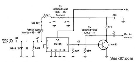
Uses Fairchild 95H90 IC to divide input signal frequency by factor of 10 up to 320 MHz. Full-wave diode limiter at input prevents damage to IC. RA is chosen to bias IC at point of maximum sensitivity; typical value is 680 ohms. Transistor amplifier provides 2-3 V P-P output. Bias resistor RB is set to make collector-base voltage 3 V; typical value is 620 ohms. Wind one lead of 4.7-ptH choke around nail 4 times, then remove nail and slip ferrite bead over end of wire before connecting it to pin 1. Keep all leads as short as possible. Article covers construction and alignment in detail.-I. Math, Math's Notes, CQ, May 1975, p 42-44 and 64. (View)
View full Circuit Diagram | Comments | Reading(4866)
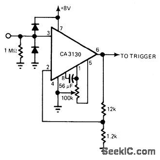
500_Hz_TONE_DETECTOR
Published:2009/7/6 1:50:00 Author:May

View full Circuit Diagram | Comments | Reading(699)
ONE_CHIP_RADAR_DETECTION_CIRCUIT
Published:2009/7/6 1:48:00 Author:May

Circuit Notes
A simple X-band. radar detector is capable of indicating changes in rf radiation strength at levels down to 2 mW/cm2. Radiation falling on the detector diode, produces a voltage at the input of an amplifter whose gain may be adjusted to vary the range at which the warning is given. The amplifier output drives a voltage comparator with a variable threshold set to a level that avoids false alarms. The comparator output is connected in the wired-OR configuration with the open collector output of an oscillator running at a frequency of 2 Hz. In the absence of a signal, the comparator output level is low, inhibiting the oscillator output stage and holding the buffer so the lamp is off. When a signal appears, the comparator output goes high, removing the lock from the oscillator which free-runs, switching the lamp on and off at 2 Hz. (View)
View full Circuit Diagram | Comments | Reading(4225)
12_V_5_MHz_COUNTER
Published:2009/7/6 1:48:00 Author:May

Portable counter is designed with low-power logic to minimize battery drain, yet provides good performance.Since most of milliwatt power drain is taken by digital readout, circuit blanks out LED display when there is no input signal. Time base divides 1-MHz crystal oscillator frequency down to desired enable time, up to tOs, using 31/2 MC14518 dual decade counters connected in ripple-through mode. Actual counting of input signal codes is also done with MC14518 counters.Latches and BCD to 7-segment decoders use MC14511s. Enable line tums first counter on and off for precise enable time period. Strobe line transfers count into memory of MC14511 latch decoder, and control line resets MC14518 decade counters for next count cycle. Displays are Monsanto MAN-4 LEDs. Article traces circuit operation in detail and gives timing diagram.-D. Aldridge, CMOS Counter Circuitry Slashes Battery Power Requirements, EDN Magazine, Oct. 20, 1974, p 65-71.
(View)
View full Circuit Diagram | Comments | Reading(2420)
| Pages:1062/2234 At 2010611062106310641065106610671068106910701071107210731074107510761077107810791080Under 20 |
Circuit Categories
power supply circuit
Amplifier Circuit
Basic Circuit
LED and Light Circuit
Sensor Circuit
Signal Processing
Electrical Equipment Circuit
Control Circuit
Remote Control Circuit
A/D-D/A Converter Circuit
Audio Circuit
Measuring and Test Circuit
Communication Circuit
Computer-Related Circuit
555 Circuit
Automotive Circuit
Repairing Circuit