
Circuit Diagram
Index 1071
FAST_15_V_BLINKER
Published:2009/7/5 23:28:00 Author:May
Addition of 1K resistor between pins 4 and 8 of National LM3909 IC in creases flash rate to about 3 times that obtainable when 300 μF is connected between pins 1 and 2. Modification of external connections gives choice of 3K, 6K, or 9K for internal RC resistors.- Linear Applications, Vol, 2, National Semiconductor, Santa Clara, CA, 1976, AN-154 ,p 2.
(View)
View full Circuit Diagram | Comments | Reading(491)
l00_MC_NOISE_FIGURE_TEST_SET
Published:2009/7/23 21:54:00 Author:Jessie
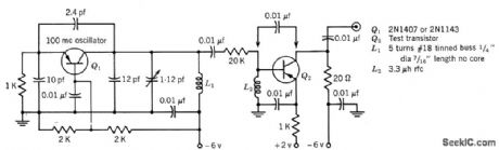
Used in measuring upper noise-corner frequency of transistors, by measuring small-signal short-circuit forward current transfer ratio (common emitter) h-fe or f-T.-Texas Instruments, Transistor Circuit Design, McGraw-Hill, N.Y., 1963, p 305. (View)
View full Circuit Diagram | Comments | Reading(682)
20_Hz_TO_200_kHz
Published:2009/7/5 23:27:00 Author:May

Variable-frequency RC-tuned oscillator uses FETs with Wien-bridge frequency-determining network, Identical resistors accurateto at Ieast 1% are switched in pairs to change range. Dual 365-pF variable capacitor C2 is used for tuning in each range. Can be calibrated against standard audio frequency with CRO set up for Lissajous figures, or calibrated with high-precision AF meter connected to AF output terminals.-R. P. Turner, FET Circuits, Howard W. Sams, Indianapolis, IN, 1977, 2nd Ed., p 132-134. (View)
View full Circuit Diagram | Comments | Reading(1699)
D_A_converter_with_0__to__10_V_unipolar_voltage_output
Published:2009/7/23 21:54:00 Author:Jessie
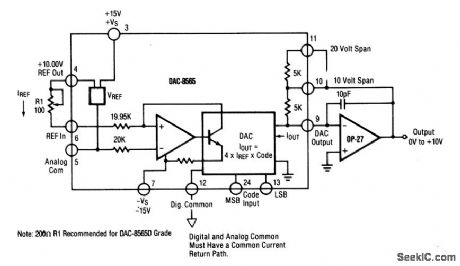
This circuit shows a DAC/op-amp combination that is used to provide a 0- to +10-V unipolar output. Pin 8 should be grounded if it is not used for trimming. To calibrate, turn all bits on (+5 V) and adjust R1 until the output is +9.9976 (full scale should be adjusted to 1 LSB less than +10.000V).If +10.2375V full scale is desired (exactly 2.5 mV/bit), insert a 120-Ω resistor in series with the gain resistor at pin 10 to the Op-amp output. If a 0- to a +5-V output is desired, tie pin 11 to pin 9, rather than to pin 10, and adjust the full scale to +4.9988 V. (View)
View full Circuit Diagram | Comments | Reading(720)
146000_147995_kHz_SYNTHESIZER_1
Published:2009/7/5 23:26:00 Author:May

Designed for use with Drake TR-33C transceiver.Circuit has built-in offset providing choice of any 5-kHz-spaced channl in frequency range for transmit and receive frequencies. Only two crystals are required. Desired frequency can be entered with BCD thumbwheel switches. Tuneup and testing procedures are given. Dt is 1N5530, D2 is 1N5144, and other diodes can be 1N914 or equivalent. Unmarked bipolar transistors are fast-switching silicon types; NPNs can be 2N2222, and PNPs can be 2N4403.-J. Moell, Super Deluxing the TR-33, 73 Magazine, April 1978, p 72-74. (View)
View full Circuit Diagram | Comments | Reading(1628)
6_V_OR_15_V_INDICATOR
Published:2009/7/5 23:26:00 Author:May

Uses DigiKey LM3909N flasher/oscillator to drive LED at 2 Hz as ON/OFF indicator for battery-operated devices. For 6-V battery, CT is 400 μF, Rs is 1000 ohms, and RFB is 1500 ohms. For 15 V, coffe-sponding values are 180, 3900, and 1000. Battery life is essentially same as shelf life.-C.Shaw, ON-OFF Indicator for Battery Device,QST, March 1978, p 41-42. (View)
View full Circuit Diagram | Comments | Reading(840)
POSITIVE_LOGIC_LAMP_DRIVER
Published:2009/7/23 21:54:00 Author:Jessie

Turns on lamp for zero or positive control pulse at A. Negative pulse at B tests condition of circuit and lamp.-A. E. Popodi, Reliable Repertoire Of Display Circuits, Electronics, 38:2, p 60-66. (View)
View full Circuit Diagram | Comments | Reading(522)
2_kHz_FLASHER_FOR_LED
Published:2009/7/5 23:24:00 Author:May


Single 1.5-V cell provides power for National LM3909 flasher IC that operates at high enough frequencyto appear on continuously, for use as indicator in battery portable equipment. Duty cycle and frequency of current pulses to LED are increased by changing external resistors until average energy reaching LED provides sufficient light for application. At 2 kHz, no flicker is noticeable.-P. Lefferts, Power-Miser Flasher IC Has Many Novel Applications, EDN Magazine, March 20, 1976, p 59-66. (View)
View full Circuit Diagram | Comments | Reading(649)
SINGLE_POT_WlEN
Published:2009/7/5 23:23:00 Author:May
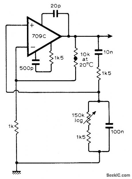
Can be tuned from 340 to 3400 Hz with single 150K Iogarithmic pot. Output is constant over tuning range. Opamp can also be 741. Components in the two arms of the Wien bridge have Iarge ratio to each other, so attenuation of network is only slightly affected by changein one of resistors.-P. C. Healy,Wien Oscillator with Single Component Frequency Control, Witeless World, Aug. 1974. p 272. (View)
View full Circuit Diagram | Comments | Reading(565)
Shanghai Sharp R-230B Computer-Type Microwave Oven Circuit
Published:2011/8/2 19:16:00 Author:Robert | Keyword: Shanghai, Sharp, Computer-Type, Microwave Oven
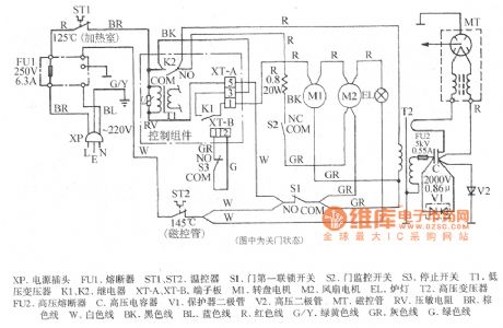
The picture shows the Shanghai Sharp R-230B computer-type microwave oven circuit.
In the picture the XP is voltage plug. The FU1 is fuse. The ST1 and ST2 are temperature controllers. The S1 is door first interlock switch. The S2 is door monitoring switch. The S3 is stopping switch. The T1 is low-voltage transformer. The K1 and K2 are relays. The XT-A, XT-B are terminal board. The M1 is rotating plate motor. The M2 is fan motor. The EL is oven lamp. The T2 is high-voltage transformer. The FU2 is high-voltage fuse. The C is high-voltage capacitor. The V1 is protector diode. The V2 is high-voltage diode. The MT is magnetron. TheRV is varistor. The BR is brown wire. The W is white wire. The BK is black wire. The BL is blue wire. The R is red wire. The G/Y is green/yellow wire. The GR is gray wire. The G is green wire. (View)
View full Circuit Diagram | Comments | Reading(1548)
LED_FLASHER
Published:2009/7/5 23:23:00 Author:May

Requires only LM3909 IC and external capacitor operating from 1.25-V nicad or other penlight cell. Circuit can be duplicated for as many additional flashing LEDs as are desired for display. Optional charging circuit uses silicon solar cells and diode for daytime charging of battery automatically.-J. A. Sandier, 11 Projects under $11, Modern Electronics, June 1978,p54-58. (View)
View full Circuit Diagram | Comments | Reading(0)
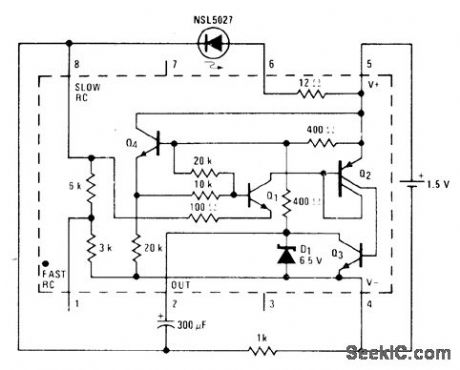
15_V_LED_FLASHER
Published:2009/7/5 23:22:00 Author:May

National LM3909 IC operating from 1.5-V battery drives NSL5027 LED in such a way that current is drawn by LED only about 1% of time. External 300-μF capacitor sets flash rate at about 1 Hz.- Linear Applications,Vol.2, National Semiconductor,Santa Clara, CA, 1976, AN-154, p 2. (View)
View full Circuit Diagram | Comments | Reading(1196)
12_V_FLUORESCENT
Published:2009/7/5 23:21:00 Author:May
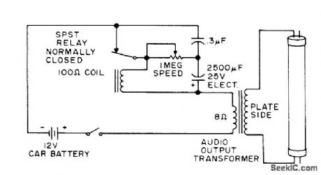
Relay acts as mechanical DC/AC converter operating off 12-V car battery.Each time relay opens, inductive kick in relay coil is stepped up by outputtransformerto high enough voltage for ionizing 24-inch fluorescent tube, giving flash that can serve as emergency flasher when car breaks down.-Circuits, 73 Magazline, June 1975, p 175.
(View)
View full Circuit Diagram | Comments | Reading(1028)
COMPARATOR_LED_FLASHER
Published:2009/7/5 23:20:00 Author:May

One section of LM339 quad comparator drives two RS2016 NPN transistors having LED load, to give simple flasher for classroom demonstrations. Circuit can be duplicated with other three sections to give four flashers. Connecting R2 to pin 1 of IC gives conventional ON/OFF flash cycle in which LED tums on and off rapidly. Connecting R2 to pin 6 makes LED tum on rapidly and tum off very slowly. C1 controls flash interval; typical value is 0.01 μF.-F. M. Mims, Integrated Circuit Projects, Vol. 5, Radio Shack, Fort Worth, TX, 1977, 2nd Ed., p 45-51. (View)
View full Circuit Diagram | Comments | Reading(1141)
146000_147995_kHz_SYNTHESIZER
Published:2009/7/5 23:19:00 Author:May
Designed for use with Drake TR-33C transceiver Circuit has built-in offset providing choice of any 5-kHz-spaced channel in frequency range for transmit and receive frequencies. Only two crystals are required. Desired frequency can be entered with BCD thumbwheel switches. Tuneup and testing procedures are given. D1 is 1N5530, D2 is 1N5144, and other diodes can be 1N914 or equivalent. Unmarked bipolar transistors are fast-switching silicon types; NPNs can be 2N2222, and PNPs can be 2N4403.-J. Moell, Super Deluxing the TR-33, 73 Magazine, April 1978, p 72-74. (View)
View full Circuit Diagram | Comments | Reading(712)
PHASE_SHIFT_SINE_WAVE
Published:2009/7/5 23:19:00 Author:May
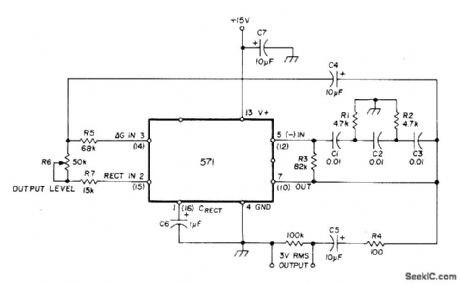
Uses NE571 analog compandor as phase-shift oscillator, with internal inverting amplifier serving to sustain oscillation. C1, C2, and C3 are timing capacitors, while R1 and R2 serve for phase-shift network.Suitable for use only as spot-frequency AF oscillator, with frequency being varied by changing values of C1, C2, and C3. Total harmonic distortion is only 0.01% at 3-V output.-W.G.Jung, Gain Control IC for Audio Signal Processing, Ham Radio, July 1977, p 47-53. (View)
View full Circuit Diagram | Comments | Reading(1781)
RED_GREEN_LED_FLASHER
Published:2009/7/5 23:18:00 Author:May

One section of LM324 quad opamp is connected as squarewave generator giving about 1 flash per second for each LED. Series resistors for LEDs have different values because they have different forward voltage requirements. If LED 2 glows between flashes, increase value of R6 slightly. Too large a value for R6 reduces flash brilliance of LED 2. Supply can be 5 or 6 V.-F. M. Mims, Semiconductor Projects, Vol. 1, Radio Shack, Fort Worth, TX, 1975, p 69-74.
(View)
View full Circuit Diagram | Comments | Reading(1544)
LED_BLINKER
Published:2009/7/5 23:18:00 Author:May

Two sections of SN7400 quad gate form MVBR operating at low enough frequency so LED status indicators come on and off slowly for visual observation of MVBR. LEDs are optional and do not affect operation of MVBR. Capacitors must be same value. Ideal for student demonstration in classroom or as Science Fair exhibit.-A. MacLean, How Do You Use ICs?, 73 Magazine, Dec.1977, p 56-59.
(View)
View full Circuit Diagram | Comments | Reading(1059)
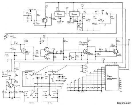
600_kHz_OFFSET_
Published:2009/7/5 23:18:00 Author:May
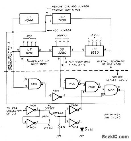
Developed for use with GLB400B frequency synthesizer which uses programmable divider and has outputs available from each flip-flop. Requires only two ICs, shown below horizontal dashed line. Select higher frequency of repeater pair on frequencyset switches. For operation at 146-147 MHz, select offset Tx to transmit on repeater input. For 147-148 MHz, select offset Rx to receive on repeater output. To operate in reverse, flip switch to other position, At center-off position, both transmit and receive are on selected frequency, with offset function disabled. LED lights only for offset.-D. Sargent, 600 kHz Offset for Frequency Synthesizers, Ham Radio, July 1978, p 98. (View)
View full Circuit Diagram | Comments | Reading(1119)
FLIP_FLOP_DRIVES_SCR
Published:2009/7/5 23:17:00 Author:May
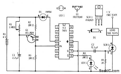
UJT relaxation oscilllator al serves as clock for driving section of 7473 dual flip-flop,One output of flip-flop-flashes Radio Shack 276-041 red LED to indicate operating status,Other output alternately triggers SCR which can be 6-A 50-V 276-1089,for COMPARATOR LED FLASHER-One section of LM339 quad comparator drives two RS2016 NPN transistors having LED load, to give simple flasher for classroom demonstrations. Circuit can be duplicated with other three sections to give four flashers. Connecting R2 to pin 1 of IC flashing lamp load. Load and SCR supply voltage depend on application but must be within SCR rating.-F. M. Mims, Semiconductor Projects,Vol. 2, Radio Shack,FortWorth,TX, 1976, p 62-70. (View)
View full Circuit Diagram | Comments | Reading(2607)
| Pages:1071/2234 At 2010611062106310641065106610671068106910701071107210731074107510761077107810791080Under 20 |
Circuit Categories
power supply circuit
Amplifier Circuit
Basic Circuit
LED and Light Circuit
Sensor Circuit
Signal Processing
Electrical Equipment Circuit
Control Circuit
Remote Control Circuit
A/D-D/A Converter Circuit
Audio Circuit
Measuring and Test Circuit
Communication Circuit
Computer-Related Circuit
555 Circuit
Automotive Circuit
Repairing Circuit