
Circuit Diagram
Index 1063
ANALOG_PEAK_DETECTOR_WITH_DIGITAL_HOLD
Published:2009/7/6 1:46:00 Author:May

Analog peak detection is accomplished by repeatedly measuring the input signal with an a/d converter and comparing the current reading with the previous reading. If the current reading is larger than the previous, the current reading is stored in the latch and becomes the new peak value. Since the peak is stored in a CMOS latch, the peak can be stored indefinitely. (View)
View full Circuit Diagram | Comments | Reading(1210)
5_MHz_FRONT_END
Published:2009/7/6 1:45:00 Author:May
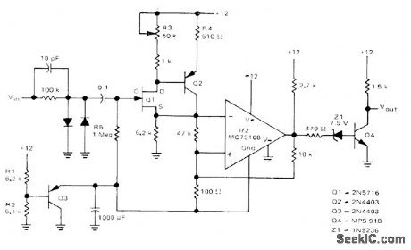
Used ahead of 5-MHz frequency counter to make input signal swing from logic 0 of 0 V to logic 1 of about 10 V as required for accurate counting of frequency for input signal having any input waveform shape and level. Input of front end has high impedance to minimize effect on input waveform. FET transistor Q1 and bipolar buffer Q2 drive Schmitt trigger using half of Motorola MC75:08 dual line receiver.-D. Aldridge, Battery-Powered 5-MHz Frequency Counter, Motorola, Phoenix, AZ, 1974, AN-717, p 5.
(View)
View full Circuit Diagram | Comments | Reading(2270)
60_kHz_WWVB_PREAMP
Published:2009/7/6 1:43:00 Author:May
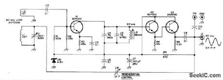


Installed in loop antenna to boost strength of 60-kHz standard-frequency broadcasts from NBS station at Boulder, Colorado, enough to drive digital frequency counter for which circuit is also given in article.Although construction details apply to double-copper shielded 54-inch,diameter circular loop, preamp can also be used with simple unshlelded wood-frame loop. Output coax supplies regulated 10 VDC for preamp, Article indudes techniques for minimizing interference from nearby TV receivers.-H. Isenring,WWNB Signal Processor, Ham Badio, March 1976, p 28.-34.
(View)
View full Circuit Diagram | Comments | Reading(1898)
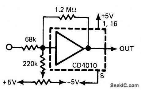
SCHMITT_TRIGGER
Published:2009/7/6 1:43:00 Author:May
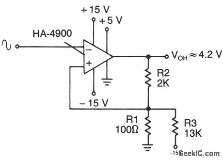
This circuit has a 100-mV hysteresis which can be used in applications where very fast transition times are required at the output, even though the signal input is very slow. The hysteresis loop also reduces false triggering because of noise in the input. (View)
View full Circuit Diagram | Comments | Reading(0)
WIDE_RANGE_PEAK_DETECTOR
Published:2009/7/6 1:41:00 Author:May

IC1 and IC2 form an inverting half-wave precision-rectifter/peak-detector circuit. Negative input-signal, swings with peaks larger than the voltage on C1, cause this capacitor to charge to the new peak voltage. The capacitor holds this voltage until a larger signal peak arrives. When the input swings high, comparator IC4 detects the zero crossing and triggers the one-shot multivibrator. The one shot closes FET switch S2, thereby causing C2 to charge to the peak voltage held on C1, during the previous half cycle. The second one shot then produces a pulse that causes FET switch S1 to discharge C1. If the next negative signal-input peak is different from the previous one, the circuit captures it and it appears at 1C3's output during the next half cycle. The peak detector thus resets itself once every input-waveform cycle. Note that the zero crossings are necessary to trigger the switches; therefore, the circuit is usable only with ac signals. (View)
View full Circuit Diagram | Comments | Reading(1751)
30_MHz_WITH_10_Hz_RESOLUTION
Published:2009/7/6 1:40:00 Author:May

Simpl ified counter design using low chip count provides multiplexing of seven digits in Fairchild display, for applications where 1-Hz resolution is not needed. 7207 oscillator/timer gives counting interval of 0.1 s, for updating display 5 times per second. Article also gives circuit of 10:1 prescaler that increases frequency limit to 300 MHz, though with 100-Hz resolution. Total counter current drain is 300 mA from regulated 5-V supply.-H. E. Harris, Simplifying the Digital Frequency Counter, Ham Radio, Feb. 1978, p 22-25. (View)
View full Circuit Diagram | Comments | Reading(546)
TIME_BASE
Published:2009/7/6 1:38:00 Author:May
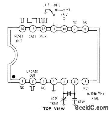
Intersil 7207 IC generates clock and housekeeping pulses required for frequency counter. With pin 11 grounded, gate output is high for 0.1 s and low for 0.1 s. With pin 11 high, gate is high 0.01 s and low 0.01 s.1.6-kHz square wave at pin 12 is useful for multiplexing displays. Update output is narrow negative-going pulse coincident with rising edge of gate output, for use in transferring countto display latches. Reset outputis used to reset counter.-D. Lancaster, CMOS Cook-book, Howard W. Sams, Indianapolis, IN, 1977, p 161. (View)
View full Circuit Diagram | Comments | Reading(973)
PRESET_FREQUENCY_ALARM
Published:2009/7/6 1:35:00 Author:May

When selected frequency occurs in Nixie-driving counter, alarm circuit triggers and locks until reset manually. Requires one SN7441 Nixie decoder/driver, one decimal-type thumbwheel switch, and one 2N3905 transistor for each digit of display in counter. Four connections are made to each counter stage to get BCD inputs A, B, C, and D for 7441. Connections can be made to 7475 quad latch in typical counter. Circuits are for 8-digit display. When display reaches digit to which switch is set, switch output is grounded. When all switch outputs are grounded, all transistors are turned on and SOP fires to actuate alarm relay. If latching is unclesirable, use medium-power NPN transistor in place of SCR.-W. L. MacDowell, Frequency Detector for Your Counter, 73 Magazine, Oct.1976 p 50-51. (View)
View full Circuit Diagram | Comments | Reading(906)
MINI_STEREO
Published:2009/7/6 1:35:00 Author:May
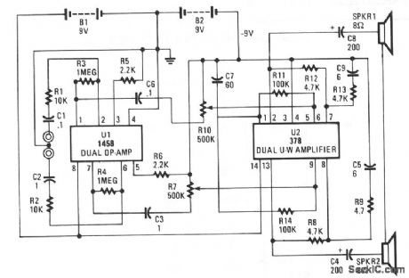
This circuit is built around two chips: the MC1458 dual op amp, configured as a preamplifier, and the LM378 dual 4-watt amplifier. The gain of the preamp is given by R3/R1 for one side and R4/R2 for the other side, which is about 100. That gain can be varied by increasing the ratios. The left and right channel inputs are applied to pins 2 and 6. The left and right outputs of U1 at pins 7 and 2 are coupled through C5/ R10 and C3/R6,respectively, to U2 to drive the two 8-Ωloudspeakers.
(View)
View full Circuit Diagram | Comments | Reading(2050)
50_MHz_WITH_1_Hz_RESOLUTION
Published:2009/7/6 1:33:00 Author:May
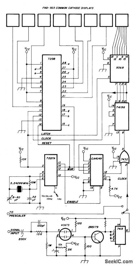
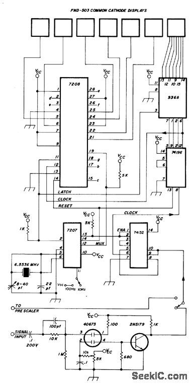
Combination of CMOS and TTL devices reduces chip count for digital frequency counter that provides 1-Hz resolution from below20 Hz to above 50 MHz. Use of 10:1 prescaler, also given in article, extends range to above 300 MHz with 10-Hz resolution. Uses Intersil 7208 CMOS seven-decade counter that includes multiplexor, decoder, drivers, and other controls for Fairchild FND.503 8-digit display. High-stability 5.24288-MHz crystal oscillator and frequency divider provide 1-s gate required for counting, outputs for synchronizing multiplexer, and short pulses for latching and resetting counters. Resolution can be decreased by factor of 10 by connecting pin 11 of 7207A to VCC, which is regulated 5 V.-H. E. Harris, Simplifying the Digital Frequency Counter, Ham Radio, Feb. 1978, p 22-25. (View)
View full Circuit Diagram | Comments | Reading(1026)
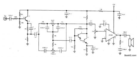
NO_COMPROMISE_PHONO_PREAMP
Published:2009/7/6 1:31:00 Author:May

Distortion figure is below 0.002 percent, overload margin is about 47 dB, and S/N ratio is 71 dB for phono amplifier. This feeds normalization amplifier whose output is set at 0 dBm by setting input gain control. Feedback components R2, R3, and C2 provide RIAA bass boost. Tone-control circuit is based on Baxandall system but has bass control turnover frequency which decreases as control approaches flat position. This allows small amount of boost at low end of audio spectrum to correct for transducer shortcomings. Article describes circuit operation in detail and gives additional circuits used for tape output, level detection, noise gate, and power supply. Transistors Tr1-Tr6 and Tr13-Tr15 are BCY71; Tr7-Tr9 and Tr16-Tr18 are MPS A06; Tr10-Tr12 and Tr19-Tr21 are MPS A56; Tr9 is BFX85 or equivalent. Circuit is duplicated for other stereo channel,-D. Self, Advanced Preamplifier Design, Wireless World, Nov. 1976, p 41-46. (View)
View full Circuit Diagram | Comments | Reading(1182)
O_3_MHz_PREAMP
Published:2009/7/6 1:31:00 Author:May
Provides wide frequency response required for amplifying 100 mV P-P input signals to 5-V level fordriving CMOS logic of frequency counter.-R. Tenny, Counter Pre-Amp Matches CMOS Logic Capability, EDN Allagazine, Sept. 20, 1976, p 114 and 116. (View)
View full Circuit Diagram | Comments | Reading(655)
PROFESSIONAL_AUDIO_NAB_TAPE_PLAYBACK_PREAMPLIFIER
Published:2009/7/6 1:31:00 Author:May
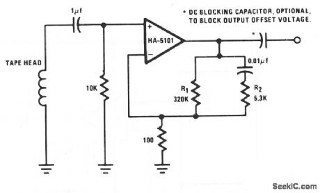
The preamplifier is configured to provide low-frequency boost to 50 Hz, flat response to 3 kHz, and high-frequency attenuation above 3 kHz. Compensation for variations in tape and tape head performance can be achieved by trimming R1 and R2.
(View)
View full Circuit Diagram | Comments | Reading(1862)
SCRATCH_RUMBLE_FILTER
Published:2009/7/6 1:30:00 Author:May

Single active filter provides two widely differing turnover frequencies, as required in audio amplifier used with phonograph. For values shown, insertion loss of filter is -6 dB at 37 Hz and at 23 kHz. Components may be switched to provide different turnover frequencies, but complete removal of filter requires considerably more complicated switching.-P. I. Day, Combined Rumble and Scratch Filter, Wireless World, Dec. 1973, p 606. (View)
View full Circuit Diagram | Comments | Reading(796)
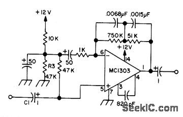
SPLIT_SUPPLY_PHONO_PREAMP
Published:2009/7/6 1:29:00 Author:May
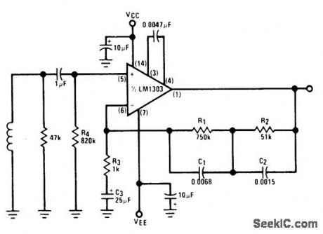
Low-noise circuit using LM1303 provides RIAA response and operates over supply voltage range of ±4.5 to ±15 V. 0-dB reference gain (1 kHz) is about 34 dB. Input is from magnetic cartridge.- Audio Handbook, National Semiconductor, Santa Clara, CA, 1977, p 2-25-2-31. (View)
View full Circuit Diagram | Comments | Reading(852)
CERAMIC_CARTRIDGE_SYSTEM
Published:2009/7/6 1:29:00 Author:May
Circuit using National LM389 opamp having three transistors on same chip provides required high input impedance for ceramic cartridge because input transistor is wired as high-impedance emitter-follower. Remaining transistors form high-gain Darlington pair used as active element in low-distortion Baxandall tone-control circuit.-“Audio Handbook,” National Semiconductor, Santa Clara, CA, 1977, p 4-33-4-37. (View)
View full Circuit Diagram | Comments | Reading(1466)
RIAA_PREAMPLIFIER
Published:2009/7/6 1:28:00 Author:May

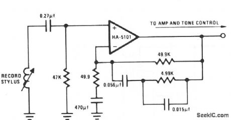
The circuit essentially provides low-frequency boost below 318 Hz and high-frequency attenuation above 3150 Hz. Recent modifications to the response standard include a 31.5-Hz peak gain region to reduce dc-oriented distortion from external vibration. (View)
View full Circuit Diagram | Comments | Reading(0)
20_Hz_HIGH_PASS_RUMBLE_FILTER
Published:2009/7/6 1:28:00 Author:May

Second-order rumble filter for phonograph amplifier has 1-dB peak and 20-Hz cutoff frequency. Design uses large resistance values to permit use of smaller and lower-cost capacitors.-D. Lancaster, Active-Filter Cookbook, Howard W, Sams, Indianapolis, IN, 1975, p 191-192. (View)
View full Circuit Diagram | Comments | Reading(716)
EQUALIZED_PREAMP
Published:2009/7/6 1:28:00 Author:May

Low-frequency boost is provided by inductance of magnetic cartridge, acting with RC network to approximate theoretical RIAA or NAB compensation as deter-mined by position of compensation switch. Input resistor is selected to provide specified loading for cartridge. Output noise is about 0.8 m VRMS with input shorted.- Signetics Analog Data Manual, Signetics, Sunnyvale, CA, 1977, p 638-639. (View)
View full Circuit Diagram | Comments | Reading(621)
MAGNETIC_CARTRIDGE_PREAMP_1
Published:2009/7/6 1:27:00 Author:May
Uses dual opamp for stereo, other half of which is connected exactly the same but with connections to pin numbers changed to those in parentheses: 6(5), 5(8), 3(11), 4(10), and 1(13).-Circuits, 73 Magazine, Sept. 1973, p 143. (View)
View full Circuit Diagram | Comments | Reading(768)
| Pages:1063/2234 At 2010611062106310641065106610671068106910701071107210731074107510761077107810791080Under 20 |
Circuit Categories
power supply circuit
Amplifier Circuit
Basic Circuit
LED and Light Circuit
Sensor Circuit
Signal Processing
Electrical Equipment Circuit
Control Circuit
Remote Control Circuit
A/D-D/A Converter Circuit
Audio Circuit
Measuring and Test Circuit
Communication Circuit
Computer-Related Circuit
555 Circuit
Automotive Circuit
Repairing Circuit