
Circuit Diagram
Index 1065
PHOTOMULTIPLIER_OUTPUT_GATING_CIRCUIT
Published:2009/7/6 1:08:00 Author:May
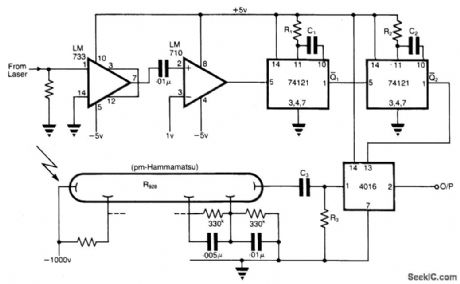
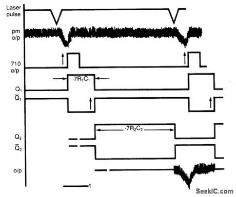
Circuit NotesThe application involves observing the light pulse emerging from a thick specimen after transillumination by a laser pulse. Pulses derived from the laser source are amplified using a Video Amplifier LM733. The reference level is set to 1 V in the comparator LM 710, to provide the necessary trigger pulses for the monostable multivibrator 74121.The laser pulses have a repetition frequency of 500 Hz and suitable values are as below:
R1= 33 k ohm, C1 = 22 pFR2 = 33 k ohm, C2 = 68 nF
The pulse width for each monostable is approximately given by tw=0.7 RC. R3 and C3 is a high pass filter. The method therefore permits the use of low cost components having moderate response times for extracting the pulse of interest. (View)
View full Circuit Diagram | Comments | Reading(1716)
TRANSIT_TIME_DIODE_UHF_SHF_TUNER
Published:2009/7/23 21:42:00 Author:Jessie
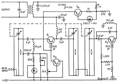
Two electronically regulated voltage sources are required to control current-tuned condition and collector voltage, using transistors OC468 and TF65 with zener diodes. One transistor operates in harmonic-generation mode as pump oscillator, comparable to parametric amplification.-U. L. Rhode, Pushing Transistors Above Their Frequency limits, Electronics, 35:25, p 46-49. (View)
View full Circuit Diagram | Comments | Reading(676)
100_Hz_TO_1_MHz_PHASE_METER
Published:2009/7/6 1:08:00 Author:May

Provides better than 2% accuracy over most of frequency range, as required for making Bode plots. Based on squaring two sine waves and comparing amount of overlap to total period of an input wave. This gives directly the amount of phase difference between input wave trains, up to 180°. Instead of measuring periods, overlap is integrated over total period to give average of ON to OFF times that can be read as phase difference on voltmeter. Article gives erformancespecifications and describes circuit operation in detail.-D. Kesner, IC Phase Meter Beats High Costs, EDN|EEE Magazine, Oct. 15, 1971, p 49-52. (View)
View full Circuit Diagram | Comments | Reading(836)
Lighting (Contd.) Circuit Principle Diagram of Liberation CA6440 Series Light Buses
Published:2011/7/20 0:10:00 Author:Michel | Keyword: Light Buses, Lighting (Contd.) Circuit, Principle Diagram
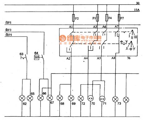
62-fog lamp,63-switch of fog lamp,64-brake light switch 65 and 66一brake light 67-tail light,68 and 69- headlamp (high beam),70 and 71-headlamp(distance light),72-indicator of distance light 74- front signal light,75-instrument light,76-lighting switch. (View)
View full Circuit Diagram | Comments | Reading(489)
Ac_coupled_inverting_amplifier
Published:2009/7/23 21:41:00 Author:Jessie

This circuit is the ac versionof the basic dc circuit in Fig. 10-26. (View)
View full Circuit Diagram | Comments | Reading(666)
VOLTAGE_CONTROLLED_PHASE_SHIFTER
Published:2009/7/6 1:06:00 Author:May
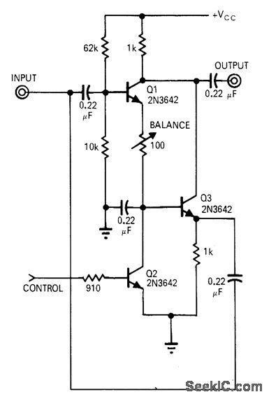
Circuit shifts carrier 180° by sensing polarity of modulating voltage. Operating range is 5 kHz to 10 MHz. Circuit can also be used to convert unipolar pulses to alternate bipolar pulses or vice versa when synchronized square wave is sup-plied to control input. With 0 V at base of Q2, Q3 will amplify RF voltage applied to input, without phase shift. To actuate switch and provide 180° phase shift, positive voltage is applied to base of Q2 so it saturates and cuts off, allowing Q1 to conduct. Output then appears across load with phase reversed.-A. H. Hargrove, Simple Circuits Control Phase-Shift, EDN Magazine, Jan. 1, 1971, p 39. (View)
View full Circuit Diagram | Comments | Reading(1682)
Radio Cassette Player and Air Conditioning Principle Diagram of Liberation CA6440 Series Light Bus
Published:2011/7/20 0:26:00 Author:Michel | Keyword: Liberation, Light Bus, Radio Cassette Player, Air Conditioning, Principle Diagram

Picture:Radio Cassette Player and Air Conditioning Principle Diagram of CA6440 Series Light Bus
75-instrument light,77-antenna of radio cassette player,78-radio cassette player ,79 and 80-loudspeaker,81-electronic clock,82-warm wind motor relay,83-heater motor,84-warm wind switch ,85-variable speed resistance ,86 and 87-micro switch ,88-drum wind (air conditioning) motor relay . (View)
View full Circuit Diagram | Comments | Reading(994)
FULL_WAVE_FEEDBACK
Published:2009/7/6 1:06:00 Author:May
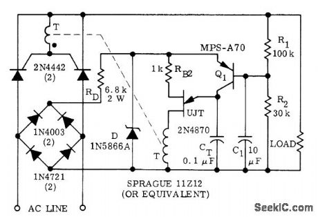
Used when average load voltage is desired feedback variable for full-wave phase control of load power. Circuit requires use of pulse transformer T.-D. A. Zinder, Unijunction Trigger Circuits for Gated Thyristors, , Motorola, Phoenix, AZ, 1974, AN-413, p 4. (View)
View full Circuit Diagram | Comments | Reading(674)
AF_PLL
Published:2009/7/6 1:04:00 Author:May

Addition of components to conventional two-transistor MVBR gives simple phase-locked loop. Tr1 and diode form logic gate that conducts during alternate half-cycles of input and VCO waveforms respectively. Output of this phase detector, when filtered, is most negative when waveforms are in phase, and most positive when they are out of phase. Once phase lock has been established, it is maintained by VCO over range of 100 to 3000 Hz.-J. B. Cole, Simple Phase-Locked Loop, Wireless World, June 1977, p 56. (View)
View full Circuit Diagram | Comments | Reading(2257)
27255_MC_TD_CRYSTAL_TRANSMITTER
Published:2009/7/23 21:41:00 Author:Jessie

Silicon-transistor Hartley oscillator modulates tunnel-diode oscillator in remote-control transmitter,- Transistor Manual, Seventh Edition General Electric co., 1964, p 356. (View)
View full Circuit Diagram | Comments | Reading(1743)
WIDE_CAPTURE_RANGE_FOR_PLL
Published:2009/7/6 1:03:00 Author:May
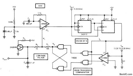
Fast wide-band phase-locked loop uses one Am686latch-ing comparator as voltage-controlled oscillator, while other is coupled with TTL latch to produce edge-triggered comparator. VCO and comparator combined with low-pass filter R1-R2-C2 form PLL When locking fails, UJT causes VOUT to scan, repetitively sweeping all frequencies in VCO range until lock is restored,Capture and locking ranges are both equal at ±60% for 5 MHz input.-M. C. Hahn, PLL’s Capture Range Equals Its Locking Range, EDN Magazine, Sept. 20, 1977, p 117 and 119-120. (View)
View full Circuit Diagram | Comments | Reading(1319)
Cigar Lighter,Wiping and Washing Circuit Principle Diagram of Liberation CA6440 Series Light Buses
Published:2011/7/20 0:56:00 Author:Michel | Keyword: Liberation, Light Buses, Cigar Lighter, Wiping, Washing, Principle Diagram

Picture:Cigar Lighter,Wiping and Washing of CA6440 Series Light Buses
89-drum wind (air conditioning) motor ,90-temperature control switch ,91-low voltage switch ,92-high voltage cutout switch,93-compressor electromagnetic clutch ,94-cigar lighter,95-washer motor,96-washing motor switch ,97-wiper,98-wiper switch,100-air conditioning floodlight ,Fl-Fl4一fuse.
(View)
View full Circuit Diagram | Comments | Reading(820)
8_bit_straight_binary_D_A_converter
Published:2009/7/23 21:41:00 Author:Jessie
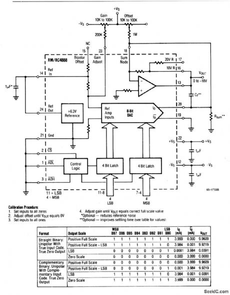
This circuit uses a DAC-4888 and a few external components to form a stand-alone, 0- to + 10-V, D/A converter with both gain and offset adjustments for calibration. (View)
View full Circuit Diagram | Comments | Reading(559)
0_90°_SHIFTER
Published:2009/7/6 1:02:00 Author:May
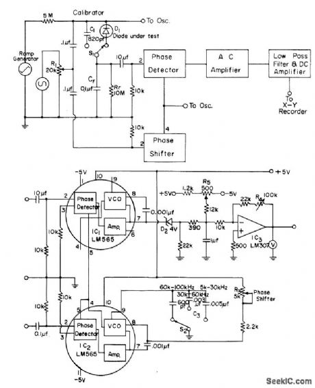
Used in automatic plotter for measuring capacitance-voltage characteristics of Schottky barrier solar cells. Diode under test is connected as shown in block diagram. Phase of square-wave output from IC, can be shifted continuously from 0 to 90° by adjusting R3. Article gives ramp circuit and design equations.-J. T. Lue, An Automatic C-V Plotter and Junction Parameter Measurements of MIS Schottky Barrier Diodes, IEEE Journal of Solid-State Circuits, Aug. 1978, p 510-514. (View)
View full Circuit Diagram | Comments | Reading(571)
PHASE_LOCKED_100_kHz_REFERENCE
Published:2009/7/6 1:01:00 Author:May

Uses 4-MHz crystal in oscillator, with voltage-variable capacitor VVC in parallel with fixed and variable capacitors for setting frequency precisely. Varicap or silicon diode can also be used for VVC. Control voltage for WC is developed by Motorola MC4044P phase-frequency detector and associated MPSA20 amplifier and filter. 7473 and 7490 ICs divide 4-MHz signal by 4 and then by 10 to give 100 kHz. Main output can be further divided with additional 7490s, down to 60 Hz for driving electric clock if desired. Adjust C3 and R1 for symmetrical square wave at pin 1 of MC4044P, with clean leading and trailing edges. Typical values are 68 pF for C3 and 300K for R1, but values will depend on transistors used. Transistor types are not critical. Gates U2B and U2C with Q3 form lock indicator circuit that turns on LED when 4-MHz oscillator is phase-locked to output of external high-stability 100-kHz frequency standard. U1 and U2 are SN7400.-C. A. Harvey, How to Improve the Accuracy of Your Frequency Counter, Ham Radio, Oct. 1977, p 26-28. (View)
View full Circuit Diagram | Comments | Reading(845)
Voltage_reference
Published:2009/7/23 21:41:00 Author:Jessie
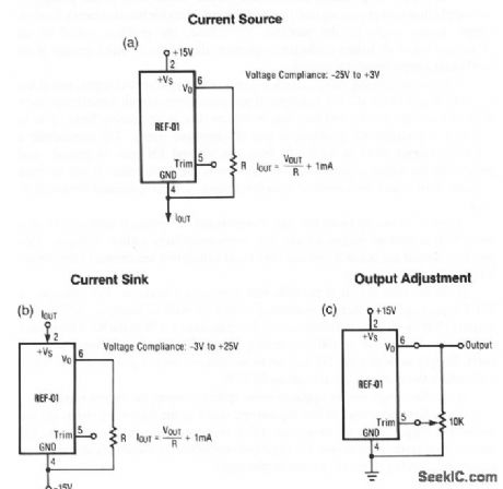
Figures 4-1A and 4-1B show an REF-01 connected as a current source, and current sink, respectively. The REF-01 trim terminal can be used to adjust the output voltage over a 10-V±300-mV range (Fig. 4-1C). This permits the output to be set at exactly 10.000 V or to 10.240 V for binary operation. (View)
View full Circuit Diagram | Comments | Reading(0)
SINE_WAVE_WIEN
Published:2009/7/6 0:58:00 Author:May
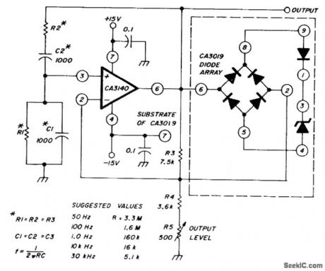
Uses CA3140 opamp and diode array to generate low-distortion sine waves. Table gives values recommended for R and C to obtain frequencies from 50 Hz to 30 kHz. Use of zener diode clamp for amplitude control gives fast AGC.-W. Jung, An IC Op Amp Update, Ham Radio, March 1978, p 62-69. (View)
View full Circuit Diagram | Comments | Reading(998)
Microprocessor_supervisor_with_internal_backup_battery
Published:2009/7/23 21:41:00 Author:Jessie
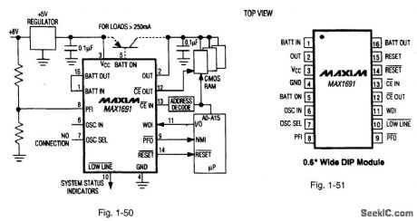
Figures 1-50 and 1-51 show a typical application circuit and pin configuration, respectively, for the MAX1691. The IC switches over to an internal backup battery to provide write protection and a watchdog function. The internal 3-V 125-mAh lithium battery connects to the supervisory circuit through external pin strapping (to minimize battery drain during shipping.) The IC is shipped in special nonconductive material. Storing the IC in conductive foam will discharge the internal battery. The power-OK/reset time delay is 200 ms, and standby current is 1μA, with a typical 35-μA operating current. On-board gating of the chip-enable signals has a maximum delay of 10 ns. MAXIM NEW RELEASES DATA BOOK, 1995, P. 5-7. (View)
View full Circuit Diagram | Comments | Reading(691)
555 Temperature/Frequency Converter Circuit (two)
Published:2011/8/1 23:39:00 Author:Zoey | Keyword: Temperature, Frequency Converter, circuit
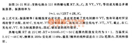
As shown in the picture 24-31, this conversion circuit consists of a 555, and thermosensitive resistances RT, R1, C1, VT1 and VT2, constituting an astable multi-vibrator. The oscillation frequency can be calculated as following formula:
f≈1.44/(2RT+2R1)C1
From the formula above, we can conclude that oscillation frequency varies as temperature change when internal resistance in tube caused by saturation and conduction of charge loop VT1 is neglected. While C1 is charged, VT1 will be saturated and conducted, while C1 is discharging, pin 3 will be in low level and VT2 and VT1 will cease to work. While C1 is charging, VT1 will offer power as a constant current source, therefore,the sawtooh wave will have a good linearity.
If temperature of thermosensitive resistances RT reaches 25℃,RT=5000Ω,variation proportion of internal resistance is about 9:1 when in 0℃~50℃. When temperature ascends to 2.8℃~46℃,frequency will range from 38Hz to 114Hz, liner error of temperare/frequeny will be ±1Hz and linearity will be excellent.
(View)
View full Circuit Diagram | Comments | Reading(964)
Ac_coupled_noninverting_amplifier
Published:2009/7/23 21:41:00 Author:Jessie

This circuit is the ac version of the basic dc circuit in Fig. 10-27. (View)
View full Circuit Diagram | Comments | Reading(746)
| Pages:1065/2234 At 2010611062106310641065106610671068106910701071107210731074107510761077107810791080Under 20 |
Circuit Categories
power supply circuit
Amplifier Circuit
Basic Circuit
LED and Light Circuit
Sensor Circuit
Signal Processing
Electrical Equipment Circuit
Control Circuit
Remote Control Circuit
A/D-D/A Converter Circuit
Audio Circuit
Measuring and Test Circuit
Communication Circuit
Computer-Related Circuit
555 Circuit
Automotive Circuit
Repairing Circuit