555 Circuit
555 Temperature/Frequency Converter Circuit (two)
Published:2011/8/1 23:39:00 Author:Zoey | Keyword: Temperature, Frequency Converter, circuit | From:SeekIC


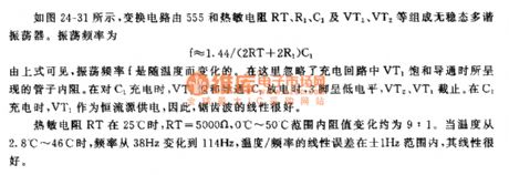
As shown in the picture 24-31, this conversion circuit consists of a 555, and thermosensitive resistances RT, R1, C1, VT1 and VT2, constituting an astable multi-vibrator. The oscillation frequency can be calculated as following formula:
f≈1.44/(2RT+2R1)C1
From the formula above, we can conclude that oscillation frequency varies as temperature change when internal resistance in tube caused by saturation and conduction of charge loop VT1 is neglected. While C1 is charged, VT1 will be saturated and conducted, while C1 is discharging, pin 3 will be in low level and VT2 and VT1 will cease to work. While C1 is charging, VT1 will offer power as a constant current source, therefore,the sawtooh wave will have a good linearity.
If temperature of thermosensitive resistances RT reaches 25℃,RT=5000Ω,variation proportion of internal resistance is about 9:1 when in 0℃~50℃. When temperature ascends to 2.8℃~46℃,frequency will range from 38Hz to 114Hz, liner error of temperare/frequeny will be ±1Hz and linearity will be excellent.
Reprinted Url Of This Article:
http://www.seekic.com/circuit_diagram/555_Circuit/555_Temperature_Frequency_Converter_Circuit_two.html
Print this Page | Comments | Reading(3)

Article Categories
power supply circuit
Amplifier Circuit
Basic Circuit
LED and Light Circuit
Sensor Circuit
Signal Processing
Electrical Equipment Circuit
Control Circuit
Remote Control Circuit
A/D-D/A Converter Circuit
Audio Circuit
Measuring and Test Circuit
Communication Circuit
Computer-Related Circuit
555 Circuit
Automotive Circuit
Repairing Circuit
Code: