Basic Circuit
VOLTAGE_CONTROLLED_PHASE_SHIFTER
Published:2009/7/6 1:06:00 Author:May | From:SeekIC

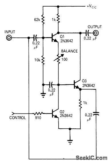
Circuit shifts carrier 180° by sensing polarity of modulating voltage. Operating range is 5 kHz to 10 MHz. Circuit can also be used to convert unipolar pulses to alternate bipolar pulses or vice versa when synchronized square wave is sup-plied to control input. With 0 V at base of Q2, Q3 will amplify RF voltage applied to input, without phase shift. To actuate switch and provide 180° phase shift, positive voltage is applied to base of Q2 so it saturates and cuts off, allowing Q1 to conduct. Output then appears across load with phase reversed.-A. H. Hargrove, Simple Circuits Control Phase-Shift, EDN Magazine, Jan. 1, 1971, p 39.
Reprinted Url Of This Article:
http://www.seekic.com/circuit_diagram/Basic_Circuit/VOLTAGE_CONTROLLED_PHASE_SHIFTER.html
Print this Page | Comments | Reading(3)

Article Categories
power supply circuit
Amplifier Circuit
Basic Circuit
LED and Light Circuit
Sensor Circuit
Signal Processing
Electrical Equipment Circuit
Control Circuit
Remote Control Circuit
A/D-D/A Converter Circuit
Audio Circuit
Measuring and Test Circuit
Communication Circuit
Computer-Related Circuit
555 Circuit
Automotive Circuit
Repairing Circuit
Code: