
Circuit Diagram
Index 1067
DAC_high_current_controller
Published:2009/7/25 5:38:00 Author:Jessie
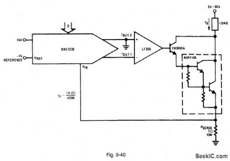
Figure 9-40 shows a DAC1230 connected to provide digital control of a 1-A current sink. Such a circgit can be used for heater control, stepper-motor torque compensation, and automatic test equipment. The largest source of nonlinearity in this circuit is the stability of the current-sensing resistance (with changes in power dissipation). The sensing resistance should be kept as low as possible to minimize this effect. The reference voltage must be reduced (to -1 V, as shown) to maintain the output-current range. The triple Darlington is used to minimize the base-current flowing through the sensing resistance, while simultaneously maintaining the collector current flow to the load. NATIONAL SEMICONDUCTOR, APPLICATION NOTE 271, 1994, P. 669. (View)
View full Circuit Diagram | Comments | Reading(755)
9_MHz_LINEAR_VCO
Published:2009/7/6 0:43:00 Author:May

U1A and U1C of RCA CA3046 transistor array form emitter-coupled oscillator. Portion of U1A current is diverted through U1B and L1, producing magnetic flux that reduces effective inductance of resonating coil L2. Output frequency is varied in direct pro portion to voltage applied at A. L1 is 23 turns on 3/4-inch Teflon form 2 inches long, with 4 turns wound between windings for L2. VR1 is 1N3828 6.2-V zener. Circuit must be well grounded and shielded to avoid hum pickup by input, which could modulate output.-D. G. Stephenson, A Second Look at Linear Tuning, OST, March 1977, p 40-41. (View)
View full Circuit Diagram | Comments | Reading(1389)
8_A_positive_adjustable_current_regulator
Published:2009/7/23 23:55:00 Author:Jessie
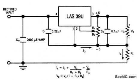
This circuit uses the LAS39U voltage-regulator IC (Fig. 7-51) as an adjustable-current regulator. Characteristics are shown in Fig. 7-50B, 7-50C, and 7-50D. (View)
View full Circuit Diagram | Comments | Reading(616)
1_MHz_SERIES_MODE_CRYSTAL
Published:2009/7/6 0:42:00 Author:May

Motorola MC1553 video amplifier provides wide band-width and output swing capability needed for high-frequency master clock or local oscillator in many system designs. Positive feedback is injected through crystal to input pin 1. Output is taken from pin 7 which is buffered internally from oscillator by gain and emitter-follower stages. Brute-force pi filter at output extracts desired fundamental frequency.- A Wide Band Monolithic Video Amplifier, Motorola, Phoenix, AZ, 1973, AN-404 , p 9. (View)
View full Circuit Diagram | Comments | Reading(750)
Single_chip_audio_amplifier_BTL_015W
Published:2009/7/23 23:55:00 Author:Jessie

This circuit make use of the bridge-tied load (BTL) principle to achieve low-voltage operation without sacrifice of output power ,The circuit operates with battery supplies from 6V down to 1.6V ,and draws low quiescent current (typically 3.2mA with 3-V supply).Closed-loop voltage gain is 32dB with connections, as shown (floating differential input ,3-Vsupply and 32-Ω load).Output is reduced to 0.14 when supply is reduced to 3V (with 32-Ω load). (View)
View full Circuit Diagram | Comments | Reading(890)
NOISE_SQUELCH
Published:2009/7/23 23:00:00 Author:Jessie
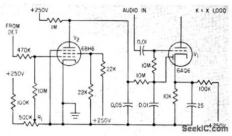
When negative-going signal is received from detector, control grid of squelch tube V2 goes negative until positive bitts set by squelch control R1 is overcome. Used in Vocaline CB transceiver.-L. Solomon, Citizens Band Equipment Design, Electronics, 33:45, p 70-72. (View)
View full Circuit Diagram | Comments | Reading(1016)
65_110_MHz_OVERTONE
Published:2009/7/6 0:42:00 Author:May
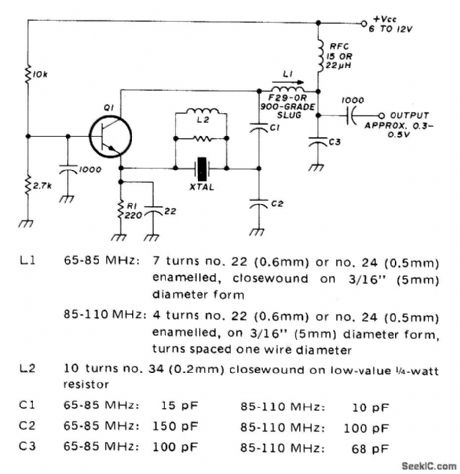
Uses fifth- or seventh-overtone crystals. RF choke formed by L2 is wound on low-value resistor to suppress lower-frequency resonances of crystal. Buffer is recommended. Circuit is slightly frequency-sensitive to supply voltage variations, so use well-regulated supply. Q1 is 2N3563, 2N3564, 2N5770, BF180, BF200, or SE1010.-R. Harrison, Survey of Crystal Oscillators, Ham Radio, March 1976, p 10-22. (View)
View full Circuit Diagram | Comments | Reading(861)
Single_chip_supply_with_parallel_operation
Published:2009/7/23 23:00:00 Author:Jessie
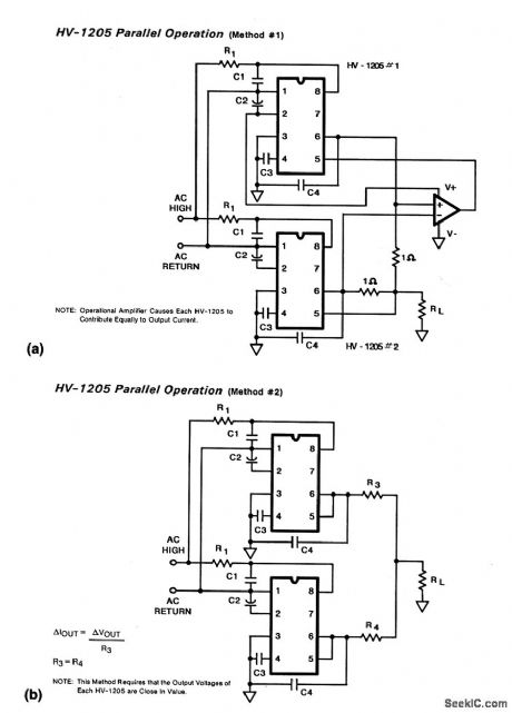
These two circuits show two HV-1205 single-chip supplies (as shown in Fig.7-6) connected in parallel to increase current capability. (View)
View full Circuit Diagram | Comments | Reading(613)
1365_Hz_TONE
Published:2009/7/6 0:41:00 Author:May
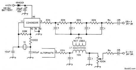
Uses 2.235-MHz crystal with counter chip to produce 136.5-Hz subaudible tone for amateur transmitter. Low-frequency square-wave output of IC is put through multistage low-pass filter to develop sine wave. Tone should be introduced into transmitter just after audio processing (after deviation control). AIternate filter is also shown; use whichever gives best performance, For other tone frequency, use crystal that is 16,384 times frequency desired.-E. Gellender and M. Marcel, P/L Tone Generator, QST, Aug. 1976. p 43. (View)
View full Circuit Diagram | Comments | Reading(551)
125_W_150_MHz_TMOS_FET_amplifier
Published:2009/7/23 22:59:00 Author:Jessie

This circuit uses an MRF174 TMOS FET, has a typical gain of 12 dB, and can survive operation into a 30:1 VSWR load at any phase angle with no damage. Notice that the output power can be reduced to loss than 1W continuously by driving the dc gate voltage negative (by adjusting R3). Figure 2-53B shows this performance feature. (View)
View full Circuit Diagram | Comments | Reading(844)
CAPACITIVELY_TUNED_WIEN
Published:2009/7/6 0:41:00 Author:May
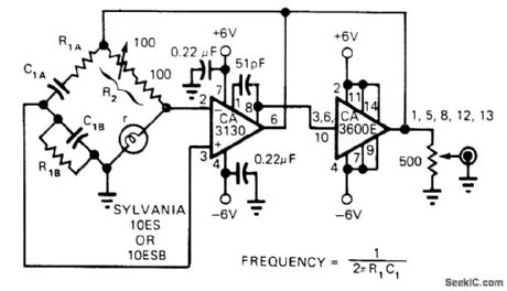
Output of amplifier is connected to apex of Wien bridge. Positive feedback is taken from junction of C1A and C1B for noninverting input of first opamp, while negative feedback is taken from other junction of bridge for inverting input. Oscillation is sustained when R2 = 2r. Nonlinearity of lamp r provides stabilization of oscillator. Frequency depends on values used for bridge components.-H. D. Olson, Wien-Bridge Oscillator Is Capacitively Tuned, EDN Magazine, Aug. 5, 1975, p 74. (View)
View full Circuit Diagram | Comments | Reading(540)
High_side_power_supplies
Published:2009/7/23 22:59:00 Author:Jessie
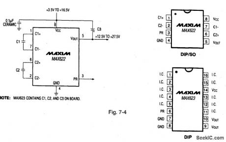
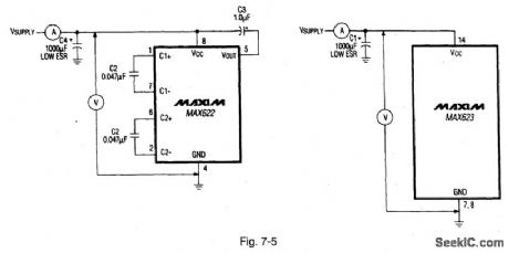
Figure 7-4 shows a MAX622 connected to generate a regulated output voltage thati s 11 V greater than the input supply voltage. The primary use is to power high-side switching and control circuits.The output current is 25 mA. with a typical qulescentcurrent of 70 μA. Figure 7-5 shows quiescent Supply current test circuits. The MAX623 has internal charge-pump capacitors.The logic level PR (power ready) output indicates when the high-side voltage reaches the proper level.MAXIM NEWRELEASES DATA Book 1992 P. 4-31 4-37. (View)
View full Circuit Diagram | Comments | Reading(724)
NAND_GATE_TIL_CRYSTAL
Published:2009/7/6 0:40:00 Author:May

Overcomes problems of poor starting performance and has upper frequency limit of 20 MHz. Suitable for applications requiring high-output aperiodic oscillator. Excellent as frequency marker.-R. Harrison, Survey of Crystal Oscillators, Ham Radio, March 1976, p 10-22. (View)
View full Circuit Diagram | Comments | Reading(2563)
CB_DECODER
Published:2009/7/23 22:59:00 Author:Jessie

Responds to telephone-dialdigital tone pulses from receiver. Rejects noise pulses and functions even when noise is stronger than desired single-tone signal. Used in mobile dial telephones.-L. G. Sands, Citizens Radio Revision Spurs Equipment Design, Electronics, 32:15, p 55-57. (View)
View full Circuit Diagram | Comments | Reading(572)
2_20_MHz_VXO
Published:2009/7/6 0:40:00 Author:May

Variable-frequency crystal oscillator plus buffer, using Signetics N7404A hex inverter or equivalent, covers 2-20 MHz. Only three inverters are used, two forming oscillator and one as output buffer. VCC is +5 V. Crystals can operate at fundamental, third, or fifth over-tone. Frequency-limiting capacitor Cp can be 15 pF. Only higher-frequency crystals can be moved useful amounts without creating instability problems. Article gives design equations and tables showing frequencies obtained with various crystals for various values of frequency controls CV (0-100 pF) and LV (0-17 μH).-B. King, Hex Inverter VXO Circuit, Ham Radio, April 1975, p 50-55. (View)
View full Circuit Diagram | Comments | Reading(2651)
AUTOMATIC_BRIGHTNESS_CONTROL
Published:2009/7/23 22:59:00 Author:Jessie
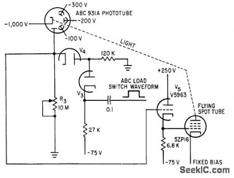
Automatic brightness control circuit intensifies scanning spot when sweep is triggered, and holds intensity constant. When spot is quiescent, output of 931A is applied to cathode follower that determines bias on 5ZP16.Phototube then sees only 10-meg load because V4 is cut off. When mark is sensed by scanner, load switching action makes V4 conduct to reduce phototube load to 120,000 ohms.-A. C. L. Brown, Flying Spot Inspects TV Rating Records, Electronics, 35:9, p 31- 34. (View)
View full Circuit Diagram | Comments | Reading(1206)
90_125_MHz_CRYSTAL
Published:2009/7/6 0:39:00 Author:May

Recmmended for VHF/UHF converters. Output is 5 to 15 mW. Crystal should be high-quality fifth- or seventh-over-tone type. Ferrite bead FB prevents undesired oscillation above 500 MHz. For best stability, allow crystal to operate at its natural series-resonant frequency and use regulated power supply.-J. Reisert, VHF/UHF Techniques, Ham Radio, March 1976, p 44-48. (View)
View full Circuit Diagram | Comments | Reading(868)
2_22_MHz_FUNDAMENTAL_MODE
Published:2009/7/6 0:37:00 Author:May
International Crystal OF-1 oscillator for fundamental-mode crystal has no LC tuned circuits and lei quires no inductors. With 28.3-MHz third-overtone crystal, output is at fundamental of crystal or about 9.43 MHz,-C. Hall, Overtone Crystal Oscillators Without Inductors, Ham Radio, April 1978, p 50-51. (View)
View full Circuit Diagram | Comments | Reading(1055)
50_1000_kHz
Published:2009/7/6 0:36:00 Author:May

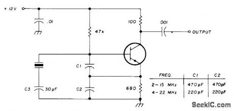
Simple single-transistor circuit provides extremely stable beat-frequency oscillator for which frequency can be changed by using tank-circuit components listed in table.-Circuits, 73 Magazine, Feb. 1974, p 101. (View)
View full Circuit Diagram | Comments | Reading(1828)
OSCILLATOR_DOUBLER
Published:2009/7/6 0:36:00 Author:May
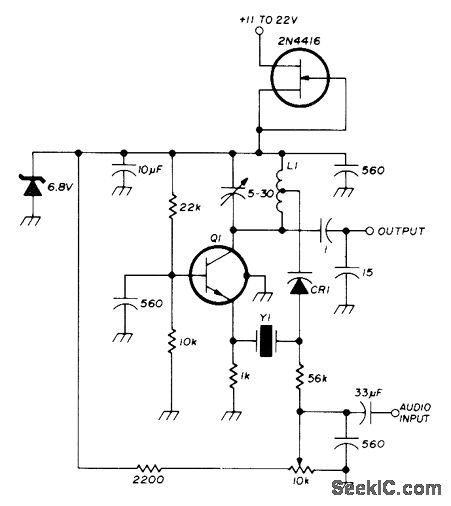
Overtone crystal oscillator circuit that frequency-doubles in transistor can be frequency-modulated or used as stable voltage-controlled crystal oscillator. Tuning range with 70-MHz third-overtone crystal is typically 30 kHz at crystal frequency or 60 kHz at output. L1 is resonant with C1 at desired out-put frequency. Tap for varactor CR1 (Motorola BB 105B or BB142) is at one-fourth total number of turns. Q1 is 2N918, BF115, HEP709, or equivalent.-U. Rohde, Stable Crystal Oscillators, Ham Radio, June 1975, p 34-37. (View)
View full Circuit Diagram | Comments | Reading(2000)
| Pages:1067/2234 At 2010611062106310641065106610671068106910701071107210731074107510761077107810791080Under 20 |
Circuit Categories
power supply circuit
Amplifier Circuit
Basic Circuit
LED and Light Circuit
Sensor Circuit
Signal Processing
Electrical Equipment Circuit
Control Circuit
Remote Control Circuit
A/D-D/A Converter Circuit
Audio Circuit
Measuring and Test Circuit
Communication Circuit
Computer-Related Circuit
555 Circuit
Automotive Circuit
Repairing Circuit