
Circuit Diagram
Index 1074
Earphone_radio
Published:2009/7/23 21:50:00 Author:Jessie
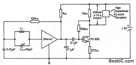
This circuit shows the ZN414Z (Fig. 2-14A) combined with an external amplifier to drive an inexpensive earpiece. This arrangement is generally cheaper than having the ZN414Z drive an expensive sensitive earpiece directly (to produce an ultra-miniature radio). The arrangement also provides for a volume control, if desired. Substitute a 250-Ω potentiometer in series with a 100-Ω fixed resistor for the 270-Ω emitter resistor. L1=80 turns of 0.3-mm diameter enamelled copper wire on a 5-cm or 7.5-cm long ferrite rod. Any value of L1/C1 that gives a high Q at the desired frequency can be used. (View)
View full Circuit Diagram | Comments | Reading(884)
Power Supply Protection Circuit of TL431
Published:2011/7/24 7:11:00 Author:Michel | Keyword: Power Supply, Protection Circuit

The a,b,c,d are power supply protection circuits of TL431.The picture (a) is constant current circuit of TL431 and the constant current I。=UREF/R2.Picture (b) is protection circuit of overvoltage and undervoltage and the voltage is equal to (1+R3/R4)UREF+UBE,when it is under voltage,the voltage is equal to (1+R1/R2)UREF when it is overvoltage.In the formula,UBE is the base-emiting voltage of VT1.Picture (c) is the current-limiting circuit and the limitting current I。=UREF/R2.Picture(d) is voltage monitoring circuit and LED displays when the voltage is lower than (1+R3/R4)UREF and higher than (1+R1/R2)UREF. (View)
View full Circuit Diagram | Comments | Reading(4305)
Universal regulated power supply circuit diagram
Published:2011/5/10 2:24:00 Author:Rebekka | Keyword: Universal regulated power supply

View full Circuit Diagram | Comments | Reading(580)
Positive and negative output voltage tracking regulated power supply integrated circuit diagram 1
Published:2011/5/10 2:23:00 Author:Rebekka | Keyword: output voltage tracking , regulated power supply

Here is the diagramof positive and negative output voltage tracking regulated power supply integrated circuit composed of CW117, CW217 and CW317. (View)
View full Circuit Diagram | Comments | Reading(716)
PCD3320P/PCD3326D Microcomputer Dialing Integrated Circuit
Published:2011/7/28 23:11:00 Author:Michel | Keyword: Microcomputer Dialing, Integrated Circuit


PCD3320P/PCD3326D is the microcomputer dial-up integrated circuit produced by Dutch Philips Company , and it is used in communication equipment and pulse dial-up circuit.
PCD3320P/PCD3326D integrated circuit contains pulse dial-up generating and key switch decoding circuits etc.This circuit adopts feet 18 DIP package and its pins functions and data are shown as the table 1.
Table 1:Pins Fuctions and Data of PCD3320P/PCD3326D IC (View)
View full Circuit Diagram | Comments | Reading(744)
Positive and negative output voltage tracking regulated power supply integrated circuit diagram 2
Published:2011/5/10 1:36:00 Author:Rebekka | Keyword: Positive and negative output voltage tracking, regulated power supply

Here is the diagram 2of positive and negative output voltage tracking regulated power supply integrated circuit composed of CW117, CW217 and CW317. (View)
View full Circuit Diagram | Comments | Reading(617)
Thermal Dissipation Control Circuit For Computer
Published:2011/7/28 7:08:00 Author:Robert | Keyword: Thermal Dissipation, Control, Computer

The Pentium 4 computer's thermal dissipation control circuit is shown in the picture. In this computer it all uses three thermal-dissipation fans. Among them, the first fan is special for the CPU's thermal dissipation. The second fan and the third fan are installed separately in the computer's front side and back side for the box's thermal dissipation. The VT is the the first channel's remote temperature sensor which is used for measuring the environment temperature. The temperature sensor in Pentium 4 CPU is used as the second channel remote temperature sensor. The ADT7460 would be connected to the power management chip produced by the Intel company through the SMBus bus. Once it has detected the over-temperature case, it would output the over-temperature interrupt signal from the ports. And then by the power management chip it would make the CPU generate a interrupt. (View)
View full Circuit Diagram | Comments | Reading(476)
Voltage_controlled_current_source
Published:2009/7/23 21:50:00 Author:Jessie
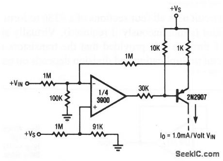
This circuit provides a variable current that is controlled by input voltage +VIN The circuit is sometimes called a transconductance amplifier, and is similar to the OTAs (operational transconductance amplifiers) that are described in chapter 11. (View)
View full Circuit Diagram | Comments | Reading(0)
Unipolar_D_A_converter
Published:2009/7/23 21:49:00 Author:Jessie
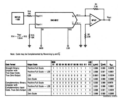
This circuit shows a DAC/op-amp combination that is used to provide unipolar positive-reference D/A converter operation. Full-scale adjustment can be made as shown in Fig. 6-39B. (View)
View full Circuit Diagram | Comments | Reading(509)
140_150_MHz_IN_5_kHz_STEPS
Published:2009/7/5 23:00:00 Author:May
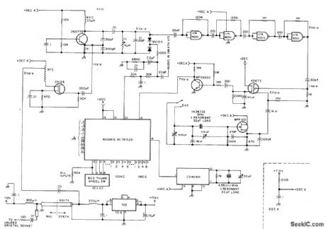
Developed for use with amateur 2-meter radios, to give direct choice of frequency by setting thumbwheel or lever switches. Phase.locked loop gives precise high-purity output. Input frequency to system is 4.5511 111-MHz reference signal from CD4060 crystal oscillator. Digital edge-triggered Hughes HCTR320 phase comparator maintains inputs of both frequency and phase coherence at lock; lock range is thus capture range, making locking on harmonics impossible. Article describes operation of circuit in detail, and gives construction details as well as circuit for keyboard entry system. Power supply is 723 precision regulator giving 7.15V.._M. I. Cohen, A Practical 2m Synthesizer, 73 Magazine, Sept, 1977, p 146-151. (View)
View full Circuit Diagram | Comments | Reading(1188)
WIDE_ARNGE_VARIABLE_OSCILLATOR
Published:2009/7/5 22:59:00 Author:May

View full Circuit Diagram | Comments | Reading(626)
Multiple regulated power supply circuit composed of LM341-5 and LM326H
Published:2011/5/10 1:09:00 Author:Rebekka | Keyword: Multiple regulated power supply circuit

View full Circuit Diagram | Comments | Reading(735)
CODE_PRACTICE_OSCILLATOR
Published:2009/7/5 22:59:00 Author:May

The inexpensive 7404 hex-inverter has enough amplification to handle a wide range of transducers. Closing the key completes the battery circuit and applies four to five volts to the 7404. Bias for the first two inverter amps (U1a and U1b) comes from the two resistors, R1 and R2, connected between their inputs and outputs. The capacitor and rheostat (R3/C1) close the feedback loop from the input to the properly-phased output.
The signal leaving Ulb drives the remaining four inverter amplifiers, U1c through U1f; they, in turn, drive the phones or speakers. The volume control potentiometers, R4-R7, may have any value front 1500 ohms to 10,000 ohms. The smaller values work best when speakers, or low impedance phones, are used. (View)
View full Circuit Diagram | Comments | Reading(0)
CLOCK_DRIVE_FOR_FLIP_FLOP_FLASHER
Published:2009/7/5 22:58:00 Author:May

555 timer connected as astable VBR generates series of timing pulses at rate determinod by value of capacitor and settifig of 1-megohm pot Provides automatic string of input pulses for driving flip-flop of dual flasher,Pulse output oestoinput capacitor C1 offlip-flop,-F.M.Mims, Integrated Circuit ,vol,5, Radio Shack,Fort Worth,TX,1977,2nd Ed,p 30-37. (View)
View full Circuit Diagram | Comments | Reading(649)
Light control regulated power supply circuit diagram composed of CW7900
Published:2011/5/10 1:10:00 Author:Rebekka | Keyword: Light control regulated power supply
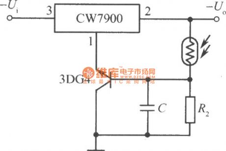
Light control circuit power supply circuit composed of CW7900(the output voltage increases in illumination). (View)
View full Circuit Diagram | Comments | Reading(555)
INEXPENSIVE_OSCILLATOR_IS_TEMPERATURE_STABLE
Published:2009/7/5 22:57:00 Author:May


The Colpitts sinusoidal oscillator provides stable output amplitude and frequency from 0°F to +150°F. In addition, output amplitude is large and harmonic distortion is low. Oscillation is sustained by feedback from the collector tank circuit to the emitter. The oscillator's frequency is determined by:
Potentiometer R3 is an output level control.
Control R1 may be used to adjust base bias for maximum-amplitude output. The circuit was operated at 50 kHz with L1 = 10mH, C1 = 3500 pF, and C2 1500 pF.
(View)
View full Circuit Diagram | Comments | Reading(840)
TUNNEL_DIODE_UHF_TUNER
Published:2009/7/23 21:49:00 Author:Jessie

Uses self-oscillating funnel-diode converter circuit.- Transistor Manual, Seventh Edition, General Electric Co., 1964, p 359. (View)
View full Circuit Diagram | Comments | Reading(527)
SIEPPER_MOTOR_RESPONSE_LOGIC
Published:2009/7/23 21:49:00 Author:Jessie
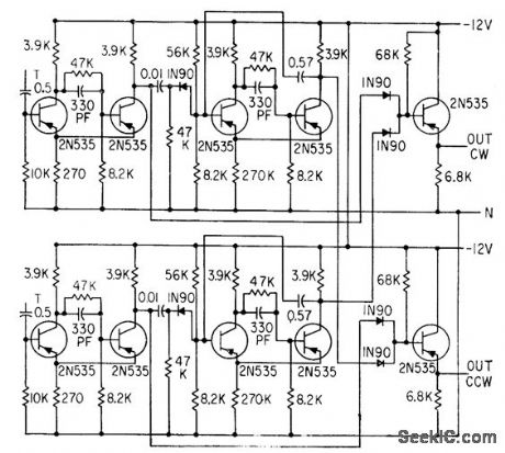
Clock-wise and counterdockwise pickoff channels each drive monostable mvbr, with output of each being added to signal of other channel. Direction-of-rotation information is supplied because pulses appear only on line whose pickoff's signal came first.-H. J Weber and M. Weiss, Analyzing Mogneticcdly Detented Stepper Servo Motors, Electronics, 33:39, p 71 -74. (View)
View full Circuit Diagram | Comments | Reading(1082)
1_kHz_OSCILLATOR
Published:2009/7/5 22:57:00 Author:May

If fine output control is desired, add the 10 K potentiometer. When the oscillator is connected to a dc circuit then connect a dc blocking capacitor in series with the potentiometer's wiper arm. (View)
View full Circuit Diagram | Comments | Reading(1293)
OUT_OF_PHASE_DOUBLE_FLASHER
Published:2009/7/5 22:57:00 Author:May

Sectionsof National MM74C908/MM74C918 dual CMOS drivel are connected as Schmitt-triigger oscilIator,with LEDs at output of each section soLEDs will flash 180°out of phase High outputcurrent capability makes circuit suitable fordrivIng two LED arrays,-, CMOS Databook, National Semiconductor,Santa Clara,CA,1977,p 5-38-5-49. (View)
View full Circuit Diagram | Comments | Reading(779)
| Pages:1074/2234 At 2010611062106310641065106610671068106910701071107210731074107510761077107810791080Under 20 |
Circuit Categories
power supply circuit
Amplifier Circuit
Basic Circuit
LED and Light Circuit
Sensor Circuit
Signal Processing
Electrical Equipment Circuit
Control Circuit
Remote Control Circuit
A/D-D/A Converter Circuit
Audio Circuit
Measuring and Test Circuit
Communication Circuit
Computer-Related Circuit
555 Circuit
Automotive Circuit
Repairing Circuit