Electrical Equipment Circuit
Earphone_radio
Published:2009/7/23 21:50:00 Author:Jessie | From:SeekIC

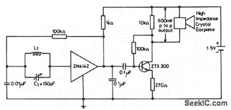
This circuit shows the ZN414Z (Fig. 2-14A) combined with an external amplifier to drive an inexpensive earpiece. This arrangement is generally cheaper than having the ZN414Z drive an expensive sensitive earpiece directly (to produce an ultra-miniature radio). The arrangement also provides for a volume control, if desired. Substitute a 250-Ω potentiometer in series with a 100-Ω fixed resistor for the 270-Ω emitter resistor. L1=80 turns of 0.3-mm diameter enamelled copper wire on a 5-cm or 7.5-cm long ferrite rod. Any value of L1/C1 that gives a high Q at the desired frequency can be used.
Reprinted Url Of This Article:
http://www.seekic.com/circuit_diagram/Electrical_Equipment_Circuit/Earphone_radio.html
Print this Page | Comments | Reading(3)

Article Categories
power supply circuit
Amplifier Circuit
Basic Circuit
LED and Light Circuit
Sensor Circuit
Signal Processing
Electrical Equipment Circuit
Control Circuit
Remote Control Circuit
A/D-D/A Converter Circuit
Audio Circuit
Measuring and Test Circuit
Communication Circuit
Computer-Related Circuit
555 Circuit
Automotive Circuit
Repairing Circuit
Code: