
Circuit Diagram
Index 1078
Multiple regulated power supply circuit composed of LM340 series
Published:2011/5/10 1:10:00 Author:Rebekka | Keyword: Multiple regulated power supply circuit

View full Circuit Diagram | Comments | Reading(653)
2.5L Engine Electronic Control Ignition Switch Wiring Circuit of Beijing CHEROKEE Light Off-road
Published:2011/7/24 7:58:00 Author:Michel | Keyword: CHEROKEE, Light Off-road, Ignition Switch, Wiring Circuit

In the circuit,ignition switch is drawn up.It is similar to general the ignition switch and it also has accessories (ACC,disconnect (OFF), operation (ON) and start (ST). The ignition switch has eight wires and connects to external circuit via plug-and-socket.And the wire of the electric plug-and-socket device is Gg2OGY/WT-sensor switch circuit 0.64 m ㎡ ash/white lines,G202OVT/YL sensor switch circuit- 0.64 m ㎡ purple/yellow line, All2RD-battery circuit 5 · 43 m ㎡ red line,A3812OR-battery circuit, one 5 43 m ㎡ orange line.And Al, A38 line is from power fusing wire Fll. (View)
View full Circuit Diagram | Comments | Reading(970)
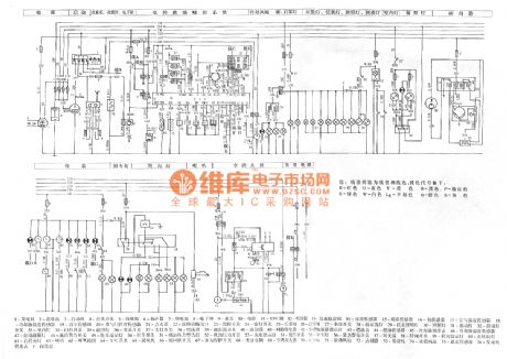
Audi A4 3.0L Engine Circuit
Published:2011/8/2 6:22:00 Author:Robert | Keyword: Audi, A4, 3.0L, Engine
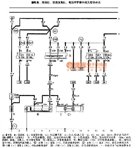
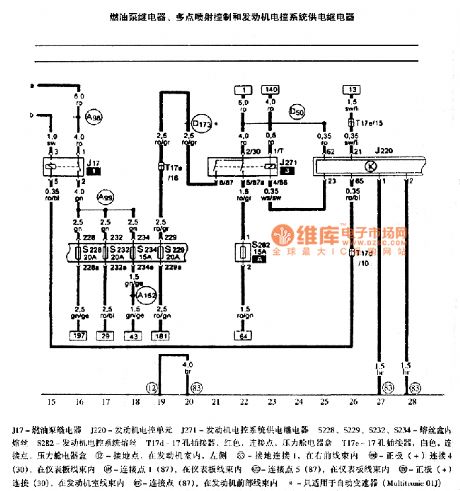
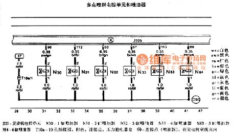
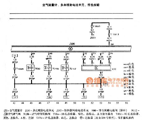

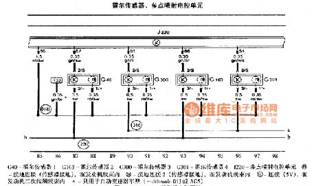
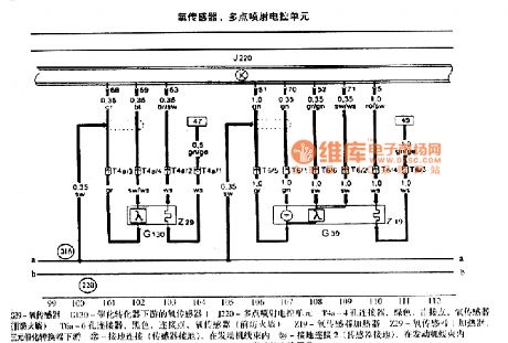
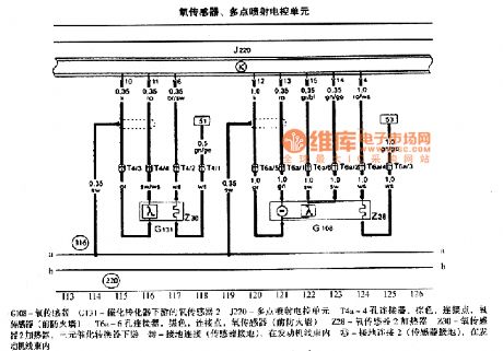
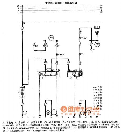
The pictures show the Audi A4 3.0L engine Circuits.
The first picture shows the battery, starting machine, AC generator, voltage adjustor, ignition starting switch.The second picture shows the fuel pump relay, multi-point injection control, engine electronic control system power supply relay.The third picture shows the multi-point injection ECU and injector.The fourth picture shows the air flow meter, multi-point injection ECU, activated carbon canister.The fifth picture shows the cooling fluid temperature sensor, multi-point injection ECU, camshaft correct timing adjustment valve, continuous cooling loop pump.The sixth picture shows the hall sensor, multi-point injection ECU.The seventh picture shows the oxygen sensor, multi-point injection ECU.The eighth picture shows the oxygen sensor, multi-point injection ECU. (View)
View full Circuit Diagram | Comments | Reading(982)
12V 10A regulated power supply circuit composed of LM340K-12
Published:2011/6/23 4:26:00 Author:Rebekka | Keyword: regulated power supply

View full Circuit Diagram | Comments | Reading(2588)
150W integrated circuit transistor hybrid emergency power supply circuit diagram
Published:2011/6/23 4:25:00 Author:Rebekka | Keyword: integrated circuit transistor, hybrid emergency power supply

150W integrated circuit transistor hybrid emergency power supply circuit diagram. (View)
View full Circuit Diagram | Comments | Reading(1130)
LM317 Current Expanding Circuit 3
Published:2011/8/1 11:02:00 Author:Robert | Keyword: Current, Expanding

The picture shows the LM317 current expanding circuit 3.
This picture is the parallel current expanding circuit's principle circuit. It is made up of two adjustable voltage regulators LM317. The input port's voltage V1=25V and the output current Io=Io1+Io2=3A. The output voltage's adjustable range is 1.2V to 22V. In this LM317 current expanding circuit, the integrated operational amplifier 741 is used to balance the two voltage regulator's output current. If the LM317-1's output current Io1 is larger than the LM317-2's output current Io2, the voltage drop on resistor R1 would increase, the operational amplifier's in-phase voltage Vp (=V1-I1R1) would decrease and the operational amplifier's output port's voltage Vao would decrease. By the adjusting port adj1 it would make the output Vo decrease and make the output current Io1 decrease so that it would be balanced. Otherwise it would be the same principle. By adjusting the resistor R5 it would adjust the output voltage's value. (View)
View full Circuit Diagram | Comments | Reading(3875)
RECEIVER_FOR_50_kHz_FM_OPTICAL_TRANSMITTER
Published:2009/7/5 22:41:00 Author:May

For maximum range, the receiver must be designed in the same manner as a radio receiver front end, since the received signals will be similar in both frequency component and in amplitude of the photodiode current. The major constraint on the receiver performance is signal to noise ratio, followed by e.m. shielding, stability, bias points, parts layout, etc. These become significant details in the final design. This receiver circuit consists of a L14G2 detector, two stages of gain, and a FM demodulator which is the tachometer circuit, modified to operate up to 100 kHz. Better sensitivity can be obtained using more stages of stabilized gain with AGC, lower cost and sensitiity may be obtained by using an H23A1 emitter-detector pair and/or by eliminating amplifter stages.
For some applications, additional filtering of the output voltage may be desired. (View)
View full Circuit Diagram | Comments | Reading(2054)
ZERO_CROSSING_DETECTOR_2
Published:2009/7/5 22:40:00 Author:May

View full Circuit Diagram | Comments | Reading(609)
Audi A6 1.8T Engine Circuit
Published:2011/8/2 6:34:00 Author:Robert | Keyword: Audi, A6, 1.8T, Engine
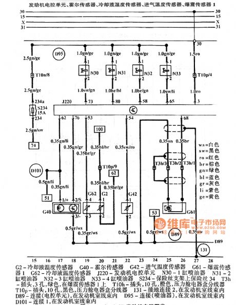
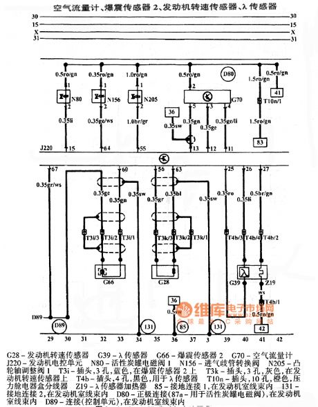
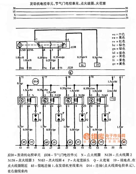


The pictures show the Audi A6 1.8L engine circuits.
The first picture shows the battery, starting machine, AC generator.The second picture shows the engine ECU, hall sensor, cooling fluid temperature sensor, intake air temperature sensor, knock sensor 1.The third picture shows the air flow meter, knock sensor 2, engine speed sensor, λ sensor.The fourth picture shows the engine ECU, throttle ECU, ignition coil, spark plug.The fifth picture shows the engine ECU, ignition switch, oil surface level/temperature sensor, fuse.The sixth picture shows the engine ECU, fuel pump relay, fuel pump, fuel meter sensor.The seventh picture shows the reversing light, engine cooling system. (View)
View full Circuit Diagram | Comments | Reading(1183)
ZERO_CROSSING_DETECTOR_WITH_TEMPERATURE_SENSOR
Published:2009/7/5 22:39:00 Author:May

View full Circuit Diagram | Comments | Reading(932)
LINEAR_OPTOCOUPLER_CIRCUIT_FOR_INSTRUMENTATION
Published:2009/7/5 22:39:00 Author:May

A dual optocoupler is used in a configuration which has the same current throughout as the LEDs. Assuming similar optocoupler features the output voltage must be equal to the noninverting input voltage. Since the op amp is within a closed loop the output voltage becomes equal to the input voltage. RC and C perform as a compensation network to prevent oscillations. (View)
View full Circuit Diagram | Comments | Reading(1590)
SERIAL_ASCII_GENERATOR
Published:2009/7/5 22:39:00 Author:May

Provides choice of two different words in standard serial ASCII asynchronous data format for troubleshooting and testing code converters and other computer peripherals. S19 gives choice of four data output patterns. R gives logic high for all 8 bits.A gives pattern determined by settings of S1-S8. B gives pattern determined by settings of S9-S16. A/B alternates words A and B. S20 gives choice of three different output modes. Mode B generates words 1 bit at a time. Mode W produces single word at rate of 110 bauds. Mode C produces continuous output of selected word pattern, for testing teleprinters and other output devices. Article covers construction and operation of circuit. IC power (+5 V) and ground pins are: 74150-24 and 12; 74157, 74161, and 74265-16 and 8; 555-8 and 1; 7474 and 7400-14 and 7.-R. J. Finger, Build a Serial ASCII Word Generator, BYTE, May 1976, p 50-53. (View)
View full Circuit Diagram | Comments | Reading(1548)
100_Hz_WIEN_BRIDGE
Published:2009/7/5 22:38:00 Author:May
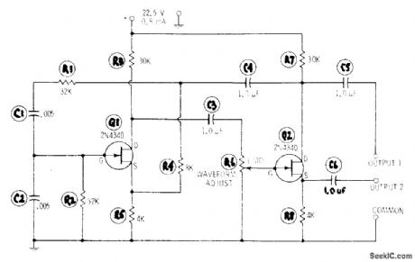


Simple RC-tuned oscillator uses only two resistors (R1 and R2) and two capacitors (C1 and C2) to set frequency.Feedback path covers both FET stages. Set R6 for best sine-wave output. For other audio frequencies, change value of R in ohms and C in farads in equation f = 1 /6.28RC where frequency is in hertz, R = R1 = R2, and C = C1 = C2.-R. P. Turner, FET Circuits, Howard W. Sams, Indianapolis, lN, 1977, 2nd Ed., p 48-50. (View)
View full Circuit Diagram | Comments | Reading(579)
ZERO_CROSSING_DETECTOR
Published:2009/7/5 22:38:00 Author:May

View full Circuit Diagram | Comments | Reading(0)
Meiri 4-Cylinder EFI A8 Engine Circuit
Published:2011/8/2 8:44:00 Author:Robert | Keyword: Meiri, 4-Cylinder, EFI, A8, Engine
The picture shows the Meiri 4-cylinder EFI A8 engine circuit.
In the picture the part 1 is generator. The part 2 is battery. The part 3 is starting machine. The part 4 is ignition switch. The part 5 is cassette players. The part 6 is speaker. The part 7 is relay. The part 8 is electronic clock. The part 9 is oil pump. The part 10 is computer. The part 11 is VSV value. The part 12 is oil injector. The part 13 is idle stabilization valve. The part 14 is speed sensor. The part 15 is knock sensor. The part 16 is oxygen sensor. The part 17 is air temperature sensor. The part 18 is cooling fluid temperature sensor. The part 19 is vacuum sensor. The part 20 is throttle position sensor. The part 21 is ignition device. The part 22 is fault diagnosis interface. And so on. (View)
View full Circuit Diagram | Comments | Reading(661)
25 ohm speakers overload protection circuit diagram
Published:2011/5/10 1:17:00 Author:Rebekka | Keyword: speakers overload protection

25 ohm speakers overload protection circuit diagramThe power of overload protection is 650mW, power supply voltage is 12V, speaker 25ohm.Part of the component specifications:VT1: Transistor NB111EH/JVT2: Transistor NR001ETV3: Transistor NA11EB/JVT4: Transistor NA12EB/J (View)
View full Circuit Diagram | Comments | Reading(1818)
IONIZATION_ALARM
Published:2009/7/5 22:38:00 Author:May

Gates in Motorola MC14572 CMOS IC form two alarm oscillators, one energized in presence of smoke at ionization chamber and other for low battery.Standby currents of circuits are low enough to give at least 1 year of operation from 750-mAh battery. R6 is adjusted to give desired smoke detection sensitivity. Gates 1 and 2 form MVBR that drives horn at astable rate of 2.5 s on and 0.2 s off in presence of smoke. When battery is low, comparator Q4-D2-D3 trips (about 10.5 V) and energizes inverter 4 of low-battery astable MVBR. DC horn is then powered at astable rate of about 1 s every 23 s to give early warning of need to change battery.-A. Pshaenich, Solid State Gas/Smoke Detector Systems, Motorola, Phoenix, AZ, 1975, AN-735, p 7.
(View)
View full Circuit Diagram | Comments | Reading(944)
50_kHz_CENTER_FREQUENCY_FM_OPTICAL_TRANSMITTER
Published:2009/7/5 22:38:00 Author:May
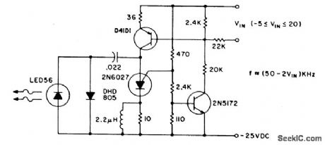
The pulse repetition rate is relatively insensitive to temperature, and power supply voltage and is a linear function of VIN, the modulating voltage. Useful information transfer was obtained in free air ranges of 12 feet (≈4m). Lenses or reflectors at the light emitter and detector increases range and minimizes stray light noise effects. Greater range can also be obtained by using a higher power output IRED such as the F5D1 in combination with the L14P2 phototransistor. Average power consumption of the transmitter circuit is less than 3 watts. (View)
View full Circuit Diagram | Comments | Reading(931)
ZERO_CROSSING_DETECTOR_1
Published:2009/7/5 22:38:00 Author:May

This detector is useful in sine wave squaring circuits and A/D converters. The positive input may either ve grounded or connected to a nulling voltage which cancels input offsets and enables accuracy to within microvolts of ground. The CMOS output will switch to within a few millivolts of either rail for an input voltage change of less than 200 μV. (View)
View full Circuit Diagram | Comments | Reading(745)
7000_7999_MHz_PLL
Published:2009/7/5 22:37:00 Author:May
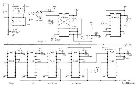
Provides output in 1-kHz steps under digital programming, except that first digit is hard-wired to 7 and does not change. VCO is Motorola MC4024, which generates square-wave output. For sineoutput, use low-pass filter at output of VCO to eliminate all frequencies above 7.999 MHz, or use different VCO. 74123 mono lengthens reset pulse generated by divide-by-N circuit. Terminals A, B, C, and D of 74192s go to grounding switches that are set to give desired division ratio, Article gives theory of PLL synthesizers YourseH!,73 Magazil,Oct,1977,p 182-188. (View)
View full Circuit Diagram | Comments | Reading(2258)
| Pages:1078/2234 At 2010611062106310641065106610671068106910701071107210731074107510761077107810791080Under 20 |
Circuit Categories
power supply circuit
Amplifier Circuit
Basic Circuit
LED and Light Circuit
Sensor Circuit
Signal Processing
Electrical Equipment Circuit
Control Circuit
Remote Control Circuit
A/D-D/A Converter Circuit
Audio Circuit
Measuring and Test Circuit
Communication Circuit
Computer-Related Circuit
555 Circuit
Automotive Circuit
Repairing Circuit