
Circuit Diagram
Index 1034
Optoisolator_driver_for_inductive_loads_with_nonsensitive_gate_triacs
Published:2009/7/22 21:00:00 Author:Jessie
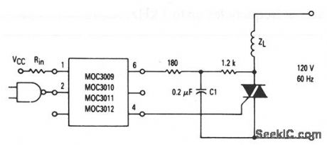
This circuit shows optoisolators (with triac driver outputs) that are used to trigger a nonsensitive-gate triac (IGT greater than 15 mA but less than 50 mA) with inductive load. C1 and the 1.2-kΩ resistor form a snubber for the triac. (View)
View full Circuit Diagram | Comments | Reading(1080)
Optoisolator_driver_for_inductive_loads_with_sensitive_gate_triacs
Published:2009/7/22 20:58:00 Author:Jessie
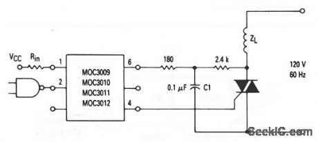
This circuit shows optoisolators (with triac driver outputs) that are used to trigger a sensitive-gate triac (IGT less than 15 mA) with inductive load. C1 and the 2.4-kΩ resistor form a snubber for the triac. (View)
View full Circuit Diagram | Comments | Reading(1479)
OPTOISOLATOR_AS_SCANNER
Published:2009/7/6 7:45:00 Author:May
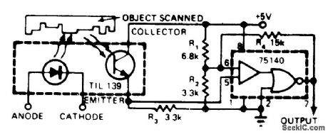
Consists essentially of Texas Instruments TIL 139 source/sensor assembly and common 75140 line receiver. Applications include response to reflected or interrupted light. With 5-V supply, output is at standard TTL levels. To make sensitivity adjustable, insert 500-ohm pot between R1 and R2. To invert output polarity, connect pin 7 of 75140 to pin 3 and take output from pin 1.--W. Grenlund, Low-Cost Photo Scanner Yields High Performance, EDN Magazine, Nov. 20, 1976, p 320. (View)
View full Circuit Diagram | Comments | Reading(834)
ISOLATED_THRESHOLD_SWITCH
Published:2009/7/6 7:43:00 Author:May
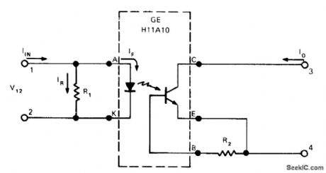
Standard photocoupler programmed with 150-ohm resistor R1 provides threshold switching function for separating high-level noise from switching-signal pulses as short as 10μs. Current-transfer ratio of phototransistor coupler is made practically zero at some arbitrary input current, and changed rapidly back to 10% or more at slightly higher level. Programming range for threshold value extends from 60 mA for 10 ohms at R1 to 3 mA for 400 ohms. Use of 2.7-megohm resistor R2 across base-emitter terminals of coupler reduces low-current gain of phototransistor. Noise currents up to 5 mA on sensing line are rejected while operating currents as low as 10 mA are accepted.-J. Cook, Photocoupler Makes an Isolated Threshold Switch, EDN Magazine, Oct. 5, 1974, p 72, 74, and 76. (View)
View full Circuit Diagram | Comments | Reading(794)
BAR_CODE_SIGNAL_CONDITIONER
Published:2009/7/6 7:42:00 Author:May

Processes low-level signal from photodiode of bar-code scanner by converting its current output to volt-age in IC1 for further amplification in IC2. Amplified signal is routed to peak holding circuits that set reference level and to comparator that outputs 0 or 1 based on reference level established. Peak values of white level and black level are held long enough to read through coded bar pattern. Difference between peak values is divided by 2 and fed to one input of comparator, while amplified signal level goes to inverting input. If signal level is greater than reference level, comparator output is 0. If signal level is less than reference level (black bar), output is 1-F. L. Merkowitz, Signal Processing for 0p-tical Bar Code Scanning, BYTE, Dec, 1976, p 77-78 and 80-84. (View)
View full Circuit Diagram | Comments | Reading(2038)
TUBE_LIFE_TEST_PULSER
Published:2009/7/22 20:54:00 Author:Jessie
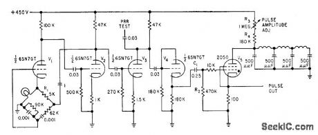
Pulse generator produces 0.25-microsec pulses at 50 v for life-testing of 1 to 15 microwave triodes at a time. Amplitude and repetition rate are adjustable within limits.-R. S. Ringland, Pulse Variable Works into Variable Load, Electronics, 31:37, p 102-103. (View)
View full Circuit Diagram | Comments | Reading(582)
400_VDC_SWITCH
Published:2009/7/6 7:40:00 Author:May
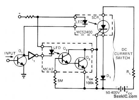
Optically isolated photo-SCR serves for switching high-voltage DC. Turnoff of SCR occurs when Q3 in MCA2 photo-Darlington shunts load current through gate, bypassing gate-cathode junction within SCR. Circuit can be operated by pulsing appropriate LEDs to turn SCR on or off. Without input signal, inverter maintains current through LED of MCA2 to keep SCR clamped off.-G. C. Riddle, Opto-Isolators Switch High-Voltage DC Cur-rent, EDN Magazine, Feb. 5, 1975, p 54. (View)
View full Circuit Diagram | Comments | Reading(1102)
GROUND_ISOLATION
Published:2009/7/6 7:39:00 Author:May
Optoisolator such as HP4320 provides ground isolation up to 200 V between systems used in spacecraft. Arrangement is effective over bandwidth of DC to 1 MHz for both DTL-and TTL-driven circuits.-W. C. Milo, Simple Scheme Isolates System Grounds Optically, EDN Magazine, Sept. 15, 1970, p 64. (View)
View full Circuit Diagram | Comments | Reading(834)
MODULATED_OPTOISOLATOR
Published:2009/7/6 7:38:00 Author:May
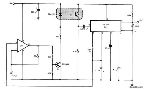
Circuit provides modulation of Fairchild FPA 103 optoisolator at about 1400 Hz and demodulation of signal from detector, to make optoisolator insensitive to strong fluorescent light without compromising performance. Rt and Ct set VCO of NE567 phase4ocked loop IC at about 1400 Hz, and 741 opamp converts triangle wave at pin 6 of PLL to square wave with 50% duty cycle for driving LED of optoisolator through Q1. Also useful with visible light systems.-R. Oliver, Improve Photo Sensors with a Phase-Locked Loop IC, EDN Magazine, April 5, 1976, p 112. (View)
View full Circuit Diagram | Comments | Reading(908)
ANALOG_ISOLATOR_1
Published:2009/7/6 7:36:00 Author:May
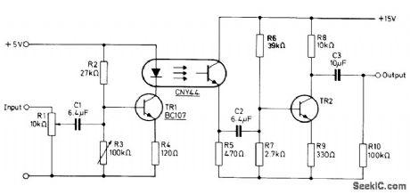
Uses Mullard CNY44 opto-isolator to transmit analog signals between units of equipment having unequal ground potentials. Circuit has 3-dB roll off point at 6 Hz and 80 kHz. Total harmonic distortion at 8 V P-P out-put is less than 1.5% between 100 Hz and 20 kHz. Output transistor TR2 is not critical.- Photocouplers, Mullard, London, 1974, Technical Information 4, TP1477, p 12. (View)
View full Circuit Diagram | Comments | Reading(3842)
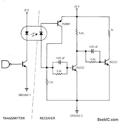
DIGITAL_ISOLATION
Published:2009/7/6 7:36:00 Author:May


Optical coupling provides complete electrical isolation between two digital circuits. Input signal as low as +4 V can make output change state, yet circuit safely handles input peaks up to +100 V without breakdown. Q1 and Q2 form current regulator that limits loop current through input of optoisolator to 7 mA. Zener CR2 provides reference voltage that defines current through R2. Schmitt trigger ST1 in output eliminates oscillations that OUTPUT could otherwise occur when slow-rise-time signal is applied to fast TTL circuits. Output changes state when input signal lights LED in optoisolator.-C. E. Mitchell, Optical Coupler and Level Shifter, EDN|EEE Magazine, Feb. 1, 1972, p 55. (View)
View full Circuit Diagram | Comments | Reading(1434)
UPC_WAND_SIGNAL_CONDITIONER
Published:2009/7/6 7:33:00 Author:May
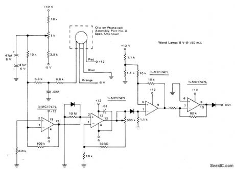
Used in recovering analog output signal of photocell assembly for reading bars of universal productcode. All four sections of two MC1747 dual opamps are used to amplify and condition photocell output so conditioned output of circuit provides TTL level 1 while wand is scanning black and 0 while scanning white. Additional processing is done by microprocessor such as MC6800.- Microprocessor Applications Manual (Motorola Series in Solid-State Electronics), McGraw-Hill, New York, NY, 1975, p 5.16-5-17. (View)
View full Circuit Diagram | Comments | Reading(668)
OPTOISOLATOR_DRIVES_1_A_POWER_TRANSIS_TOR_IC
Published:2009/7/6 7:32:00 Author:May
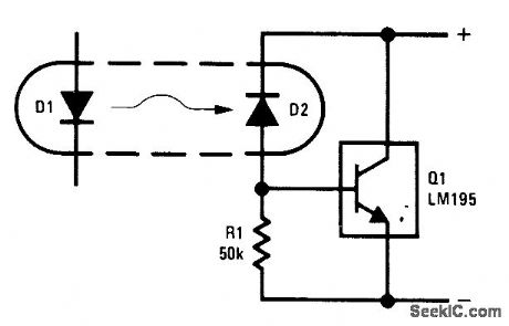
Practically any standard optoisolator provides sufficient output to meet input current requirement of power transistor IC capable of handling 1 A. With no drive, R1 absorbs base current of at, holding it off. When power is applied to LED D1, less than 20μA from photo-diode D2 is sufficient to turn LM195 fully on. Supply can be up to 42 V.- Linear Applications, Vol. 2, National Semiconductor, Santa Clara, CA, 1976, AN-110, p 5. (View)
View full Circuit Diagram | Comments | Reading(674)
ISOLATION_WITH_GAIN_COMPENSATION
Published:2009/7/6 7:32:00 Author:May

Provides total harmonic distortion under 1% while automatically adjusting for temperature-produced or other DC gain variations in opto-isolator. Output signal is sampled and fed back to FET to maintain constant AC gain. Design equations are given.-A. Billings, Optocoupler Provides Analog Isolation, EDN Magazine, Nov. 5, 1978, p 121-122. (View)
View full Circuit Diagram | Comments | Reading(558)
ANALOG_ISOLATOR
Published:2009/7/6 7:30:00 Author:May

Circuit is basically FM transmission system in which light is used as transmission medium. Transmitter uses 565 PLL as VCO for flashing LED of optoisolator at rate proportional to input voltage. Phototransistor drives amplifier having sufficient gain to apply 200 mV p-p singnal to input of receiving 565 acting as FM detector for re-creating input to transmitter. Supply can be ±6 V to ±12 V.- Signetics Analog Data Manul, Signetics, Sunnyvale, CA, 1977, p 846-847. (View)
View full Circuit Diagram | Comments | Reading(1340)
EIGHT_COMMAND_RECEIVER
Published:2009/7/22 20:53:00 Author:Jessie

Ttransistorized superheterodyne with crystal-controlled local oscillator energizes eight-reed relay, with each reed activating own transistor switch. Reeds are tuned to different frequencies between 250 and 500 cps.-R. A Baker, Rcdio-Controlled Tank for Realistic Combat Training, Electronics, 33:45, p 55-57, (View)
View full Circuit Diagram | Comments | Reading(1032)
__PHASE_TRACKING_THREE_PHASE_GENERATOR
Published:2009/7/6 7:27:00 Author:May
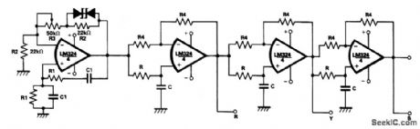
Using a single chip LM324 can, with active R-C networks, reduce the size of a 3-phase waveform generator, and prove useful in compact and stable 3-phase inverters. One quarter of an LM324 is used as a Wien bridge oscillator generating a pure sinusoidal waveform while the remaining parts of the LM324 are used as three 120° fixed phase shifters.Initially potentiometer R3 should be varied to adjust the loop gain of the oscillator in order to start the oscillator. (View)
View full Circuit Diagram | Comments | Reading(2741)
DRONE_RECEIVER
Published:2009/7/22 20:52:00 Author:Jessie
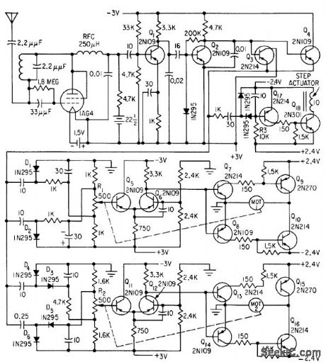
Signal from ground transmitter is received by logarithmic mode (self-quenching) superregenerative receiver. Clipper Q2 limits signal to constant level. Combinations of prr and pulse symmetry alter positions of rudder and elevator motors. Engine speed, transmitted by momentarily interrupted modulation, acts on Q17.Q18.-G. B. Herzog, Transistors Simplify Control of Target Drone, Electronics, 32:18, p 52-54. (View)
View full Circuit Diagram | Comments | Reading(1972)
TWO_MHz_SQUARE_WAVE_GENERATOR_USES_TWO_TTL_GATES
Published:2009/7/6 7:26:00 Author:May
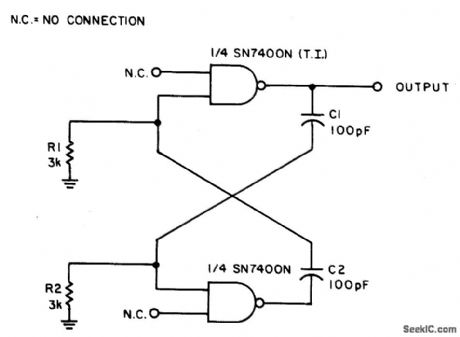
With the values shown the circuit generates a 2-MHz symmetrical square wave. Changing capacitors C1 and C2 to 0.01 μF results in a frequency of 500 Hz. For the particular integrated circuits and power supply voltages (5.0 V), the reliable operating range of R1 = R2 is 2 k ohm to 4 k ohm. (View)
View full Circuit Diagram | Comments | Reading(651)
460_MC_F_M_COMMAND_RECEIVER
Published:2009/7/22 20:48:00 Author:Jessie
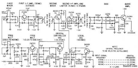
Transistorized double-conversion f-m superhet, tunable by crystal substitution in 457-462-Mc band, has 6-microvolt sensitivity for 20 db of noise quieting. Camera start and timing pulses are amplitude-modulated onto 3.5 and 12-kc carriers. After signal is detected, subcarriers are separated and pulses ore re constituted by decoder. Start pulses operate camera relays, and timing pulses lash neon lamps.-F. M. Gardner and L. R. Hawn, Camera Control System for Rocket Sled Tests, Electronics, 33:14, p 63-65. (View)
View full Circuit Diagram | Comments | Reading(976)
| Pages:1034/2234 At 2010211022102310241025102610271028102910301031103210331034103510361037103810391040Under 20 |
Circuit Categories
power supply circuit
Amplifier Circuit
Basic Circuit
LED and Light Circuit
Sensor Circuit
Signal Processing
Electrical Equipment Circuit
Control Circuit
Remote Control Circuit
A/D-D/A Converter Circuit
Audio Circuit
Measuring and Test Circuit
Communication Circuit
Computer-Related Circuit
555 Circuit
Automotive Circuit
Repairing Circuit