
Circuit Diagram
Index 1041
LIGHT_BEAM_VOICE_TRANSMITTER
Published:2009/7/6 6:02:00 Author:May
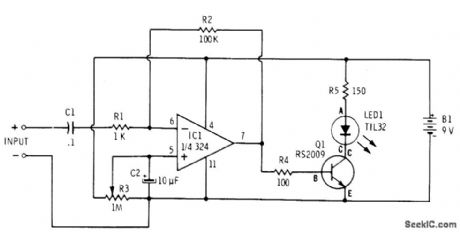
Opamp and transistor together provide amplitude modulation of LED in accordance with amplitude variations of microphone output signal. Requires only single 9-V supply. Other three sections of opamp are not used. Designed for dynamic microphone. Q1 is 2N2222 (Radio Shack 276-2009).-F. M. Mims, Optoelectronic Projects, Vol. 1, Radio Shack, Fort Worth, TX, 1977, 2nd Ed., p 34-43. (View)
View full Circuit Diagram | Comments | Reading(1953)
LOW_BATTERY_WARNING_DISCONNECTOR
Published:2009/7/6 5:59:00 Author:May

NiCad batteries are excellent rechargeable power sources for portable equipment, but care must be taken to ensure that the batteries are not damaged by overdischarge. Specifically, a NiCad battery should not be discharged to the point where the polarity of the cell is reversed and is reverse-charged by the higher-capacity cells. This reverse charging will dramatically reduce the life of a NiCad battery. This circuit both prevents reverse charging and also gives a low-battery warning. A typical low-battery warning voltage is 1 V per cell. Since a NiCad, 9-V battery is ordinarily made up of six cells with a nominal voltage of 7.2 V, a low-battery waming of 6 V is appropriate, with a small hysteresis of 100 mV. To prevent overdischarge of a battery, the load should be disconnected when the battery voltage is 1 V x (,N- 1), where N = number of cells. In this case, the low-battery load disconnect should occur at 5 V. Since the battery voltage will rise when the load is disconnected, 800 mV of hysteresis is used to prevent repeated on-off cycling. (View)
View full Circuit Diagram | Comments | Reading(663)
BASIC_COLOR_ORGAN
Published:2009/7/6 5:58:00 Author:May

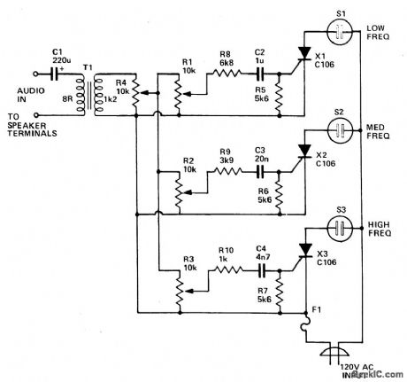
Transformer T1 can be any matching transistor type in the range of 500/500 to 2500/2500 ohms. No connections from the SCR or its components are connected to ground. For safety's sake, keep the 117-V line voltage from the amplifier connections-that is the reason for using T1. To adjust, set potentiometer R1 off and adjust the amplifier volume control for a normal listening level. Then adjust the potentiometer until the lamp starts to throb in step with the beat. (View)
View full Circuit Diagram | Comments | Reading(611)
LOW_BATTERY_PROTECTOR
Published:2009/7/6 5:58:00 Author:May
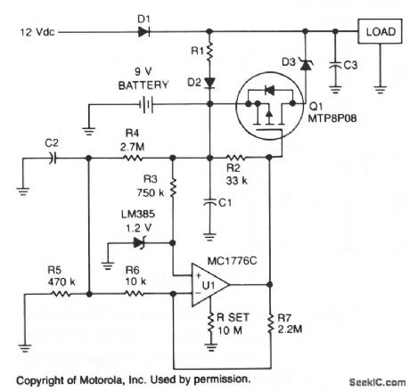
To prevent battery damage due to over-dis-charge, a low-voltage detector and switch should be included in the design of the battery backup circuit.The detector circuit should consume extremely low current. The switch should exhibit a low-voltage drop and be easy to control.
R1 and D2 provide a trickle charge for the battery. Chosen for its low forward voltage drop, Schottky diode D3 prevents forward polarization of the diode incorporated in Q1. When the battery voltage is above approximately 8 V, the output of U1 is low and Q1 is turned on. If the battery voltage falls below 8 V, the output of U1 increases and turns off Q1. (View)
View full Circuit Diagram | Comments | Reading(2256)
Lighting (Contd.) and Brake Lights Circuit Principle Diagram of Liberation CA6440 Series Light Buses
Published:2011/7/20 0:39:00 Author:Michel | Keyword: Liberation, Light Buses, Lighting, Brake Lights Circuit, Principle Diagram
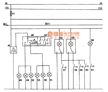
Picture:Lighting (contd.) and Brake Lights Circuit Principle Diagram of CA6440 Series Light Buses
45-flasher,46- turn signal swich,47-danger alertion switch,48 to 51一left and right direction indicator tell-tale,52 and 53-left and right indicator,54 and 55- indoor lamp,56- courtesy lamp,57-61-gate controlled switch. (View)
View full Circuit Diagram | Comments | Reading(587)
COLOR_ORGAN
Published:2009/7/6 5:56:00 Author:May
Three lights are controlled by the three channels. One light will pulse in response to the bass, another illuminates with midrange sounds, and the last lights for high notes.Four level controls allow adjustment of overall light level and each channel individually.Up to 200 watts per channel can be handled. (View)
View full Circuit Diagram | Comments | Reading(1964)
5_W_POWER_OPAMP
Published:2009/7/6 5:56:00 Author:May
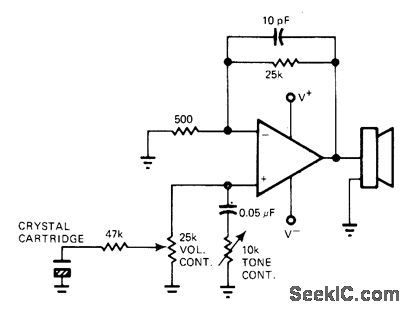

Low-cost phono amplifier using only single 591 power opamp provides 5 W into 8-ohm load with only 0.2% total harmonic distortion. With crystal cartridge, circuit has fixed gain of 50.-R. J. Apfel, Power Op Amps-Their Innovative Circuits and Packaging Provide Designers with More Options, EDN Magazine, Sept. 5, 1977, p 141-144. (View)
View full Circuit Diagram | Comments | Reading(967)
RIAA_PHONO_PREAMP
Published:2009/7/6 5:56:00 Author:May

Design procedure is given for operation from 30-V supply, using magnetic cartridge having 0.5 mV/cm/s sensitivity. Will drive power amplifier having 5 VRMS input overload limit.-“Audio Handbook,”National Semiconductor, Santa Clara, GA, 1977, p 2-25-2-31. (View)
View full Circuit Diagram | Comments | Reading(1775)
__VOX_BOX
Published:2009/7/6 5:55:00 Author:May
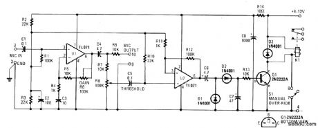
The electronic circuit in the VOX Box consists of three parts: a microphone preamplifier, a Schmitt trigger, and a relay driver. Input signals (MIC INPUT terminals) to the microphone preamplifier (U1) are amplified and fed to a THRESHOLD control (R8). When the preselected threshold voltage level is exceeded, the output of the Schmitt trigger (U2) immediately goes high. The signal from U2 is rectified and the voltage developed across C7 turns on the relay energizer transistor (Q1). That transistor action passes pull-down current through the coil of relay K1. The changing of the relay SPDT contacts can be used to either make or break an external ac or dc circuit.
(View)
View full Circuit Diagram | Comments | Reading(2054)
MAGNETIC_PICKUP_PREAMP_1
Published:2009/7/6 5:55:00 Author:May

JFET input provides proper loading for variable-reluctance magnetic phono cartridge Gain of preamp is about 35 dB at 1 kHz (100-mV output for 2.2-mV input). Dynamic range is 84 dB referenced to 1 kHz Circuit includes feedback for RIAA equalization.-“FET Databook,” National Semiconductor, Santa Clara, CA, 1977, p 6-26-6-36. (View)
View full Circuit Diagram | Comments | Reading(2494)
CERAMIC_CARTRIDGE_AMPLIFIER
Published:2009/7/6 5:54:00 Author:May
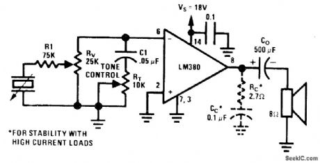
Single National LM380 forms simple amplifier with tone and volume controls for driving 8-ohm loud-speaker at outputs above 3 W. Supply voltage range is 12-22 V, with higher voltage giving higher power. Tone control changes high-frequency rolloff.- Audio Handbook, National Semiconductor, Santa Clara, CA, 1977, p 4-21-4-28. (View)
View full Circuit Diagram | Comments | Reading(1518)
SOUND_ACTIVATED_ac_SWITCH
Published:2009/7/6 5:54:00 Author:May
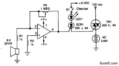
The circuit uses a 741 op amp operating as an inverting amplifier to amplify the voltage produced by an 8-ohm speaker used to detect any sounds. The feedback resistor R3, a 1-megohm potentiometer used to vary the gain of the amplifier determines the sensitivity of the circuit. When S1 is closed in the (SET) position and a sound is applied to the speaker, SCR1 is tumed on. It will remain in conduction until the anode voltage is removed by opening S1, putting it in its RESET position. (Once an SCR is turned on, the gate or trigger has no control over the circuit.) As long as the SCR conducts,the Triac, TR1, will remain on and supply voltage to the logd. (View)
View full Circuit Diagram | Comments | Reading(815)
LOW_NOISE_PREAMP
Published:2009/7/6 5:53:00 Author:May
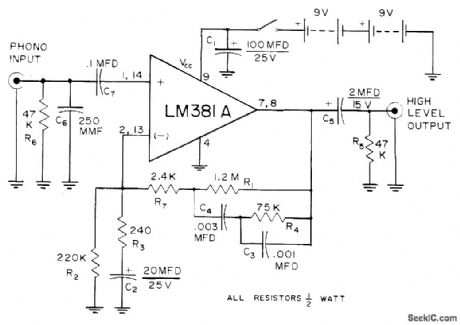
Provides dynamic range of about 80 dB for phonograph playback system, even when using highest-quality cartridge having low output. Source voltage is reduced to 18 V for National LM381A, which still provides ample signal for 2-V high-level input of stereo channel. Cross-channel isolation is better than 60 dB from 20 to 20,000 Hz.-J. P. Holm, A Quiet Phonograph Preamplifier, Audio, Oct. 1972, p 34-35. (View)
View full Circuit Diagram | Comments | Reading(896)
PREAMP_WITH_EQUALIZATION
Published:2009/7/6 5:52:00 Author:May
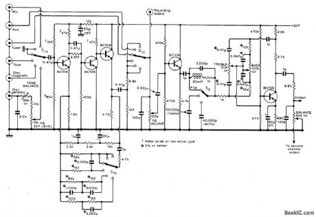
Baaed on 1966 high-performance Bailey preamp design with improved filter and tone control circuits and additional complete ceramic-pickup equalizing circuit. Equalization for magnetic pickups and other types of inputs is automatically selected by three-deck input selector switch. To avoid overloading input stage, adjust set level control to give comfortable listening level for given input when main volume control is at about half its maximum rotation. Article also gives lower-cost version for ceramic-pickup equalization and changes required in this for operation from negative supply.-B. J. Bur-rows, Ceramic Pickup Equalization, Wireless World, Aug. 1971, p 379-382. (View)
View full Circuit Diagram | Comments | Reading(1830)
SOUND_ACTIVATED_SWITCH
Published:2009/7/6 5:52:00 Author:May

The audio from Mia is amplified by Q1. Peaks of signal (adjusted by R1) greater than about 0.7 volts trigger the SCR and light lamp I1. (View)
View full Circuit Diagram | Comments | Reading(0)
RUMBLE_FILTER_1
Published:2009/7/6 5:51:00 Author:May

Used to roll off low-frequency noise associated with worn turntable and tape transport mechanisms. Gain is 1. Design procedure is given. For values shown, corner frequency is 50 Hz and slope is -12 dB per octave.- Audio Handbook, National Semi-conductor, Santa Clara, CA, 1977, p 2-49-2-52. (View)
View full Circuit Diagram | Comments | Reading(811)
MAGNETIC_PICKUP_PREAMP
Published:2009/7/6 5:50:00 Author:May
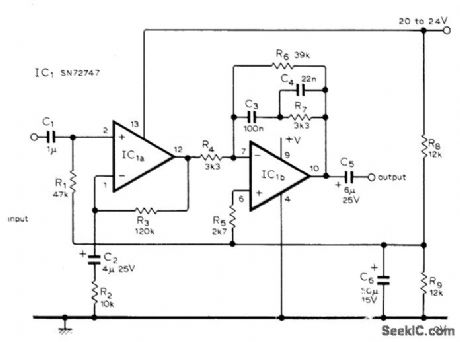
Circuit uses type 747 dual opamp, but individual 741 opamps may be used instead. Input signal is first amplified flat, after which equalization acts on both signal and noise to give improved S/N ratio. Adjust first opamp for gain of 13. Series feedback is used to minimize noise since impedance of magnetic pickup is low compared to opamp input impedance. Second opamp has frequency-dependent series feedback for RIAA compensation. Gain here is unity at 1 kHz. Out-put is about 70 mV for modern pickup having output of about 5 mV.-B. S. Wolfenden, Magnetic Pick-Up Preamplifier, Wireless World, Sept. 1976, p 81-82. (View)
View full Circuit Diagram | Comments | Reading(1807)
VARYING_FREQUENCY_WARNING_ALARM
Published:2009/7/6 5:50:00 Author:May

The output frequency changes continuously. Low frequency oscillator (Q1) modulates high frequency oscillator Q2 and its associated timing capacitor.
(View)
View full Circuit Diagram | Comments | Reading(589)
NICAD_BATTERY_ANALYZER
Published:2009/7/6 5:50:00 Author:May


Because NiCad batteries maintain a constant output voltage, it is difficult to determine how much of the battery's charge remains. The circuit provides a way of determining the capacity of a battery by draining it at a preset current to its depleted voltage of 1 V/cell. Measure the discharge time of the cells and perform a simple calculation to obtain the battery's capacity.
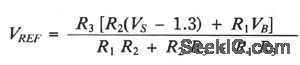
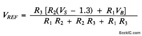
Set the drain current(ID) to 0.5C (C = battery capacity in mA/hr) by selecting an appropriate value for R4. Choose R5 such that: ID x R5 = 1 V. VREF is set so the comparator turns off the drain current and timer when the battery reaches its depleted voltage, VB (usually 1 V/cell). You calculate VREF as follows:
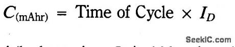
With the battery in place, activate the circuit by grounding VREF with the momentary switch. The battery drains at ID until it reachesVB, turning off the drain circuit and the timer. Hysteresis keeps the circuit from restarting. Determine the battery's capacity using the following equation:
The circuit shown tests 4.8 V, 180 mA/hr batteries. ID is 100 mA and VB is 4 V. (View)
View full Circuit Diagram | Comments | Reading(594)
INVERSE_RIAA_RESPONSE_GENERATOR
Published:2009/7/6 5:49:00 Author:May
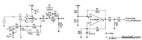
Used in design, construction, and testing of phonograph preamp. Provides opposite of play-back characteristic, Passive filter is added to output of National LM387, used as flat-response adjustable-gain block. Gain range is 24 to 60 dB, set in accordance with 0-dB reference gain (1 kHz) of preamp under test. Input is from 1-kHz square-wave generator, which can be built with other half of LM387 connected as also shown.-D.Bohn, Invese RIAA/Square Wave Generator, Audio, Feb. 1977, p 65-66. (View)
View full Circuit Diagram | Comments | Reading(1452)
| Pages:1041/2234 At 2010411042104310441045104610471048104910501051105210531054105510561057105810591060Under 20 |
Circuit Categories
power supply circuit
Amplifier Circuit
Basic Circuit
LED and Light Circuit
Sensor Circuit
Signal Processing
Electrical Equipment Circuit
Control Circuit
Remote Control Circuit
A/D-D/A Converter Circuit
Audio Circuit
Measuring and Test Circuit
Communication Circuit
Computer-Related Circuit
555 Circuit
Automotive Circuit
Repairing Circuit