
Circuit Diagram
Index 1040
Gain_of_2_drivers_for_back_terminated_coax_
Published:2009/7/22 22:44:00 Author:Jessie


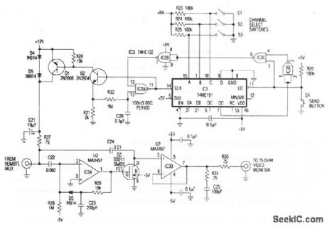
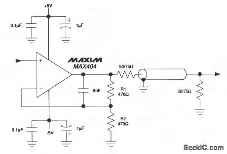
This circuit remains stable while driving unlimited capacitive video loads. As a result, flash A/D converter inputs, long-distance coaxial cables, and other larger or varying capacitive loads can be driven without output oscillation or ringing. Here, a MAX404 is connected as aback-terminated 50- or 75-Ω coax cable drive in a noninverting gain of 2,. Gain at the cable end is 1. (View)
View full Circuit Diagram | Comments | Reading(597)
LASCR_CONTROLLED_OSCILLATOR
Published:2009/7/6 6:15:00 Author:May
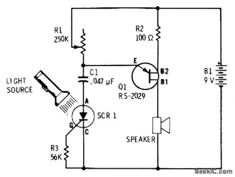
UJT relaxation oscillator having loudspeaker load produces single click each time flash of light falls on light-activated SCR Setting of R1 determines whether circuit produces series of pulses or tone burst during time light is on Oscillator frequency Increases with light intensity.-F. M. Mims, Semiconductor Proiects, Vol.2, RadioShack, Fort Worth, TX, 1976, p 71-77. (View)
View full Circuit Diagram | Comments | Reading(1582)
SOLAR_POWER_OSCILLATOR
Published:2009/7/6 6:14:00 Author:May
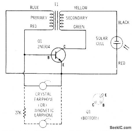
Supply voltage for single-transistor audio oscillator is generated by Radio Shack 276-115 selenium solar cell that produces about 0.35 V in bright sunlight. With cell 3 feet away from 75-W incandescent lamp, oscillator frequency is about 2400 Hz. Frequency drops as light increases. Transformer is 273-1378.-F. M. Mims, Transistor Projects, Vol. 2, Radio Shack, Fort Worth, TX, 1974, p 53-58. (View)
View full Circuit Diagram | Comments | Reading(960)
Precision_absolute_value_circuit
Published:2009/7/22 22:43:00 Author:Jessie
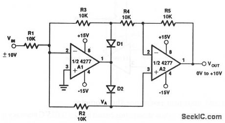
The values and types for D1 and D2 are not critical, but both diodes should be the same, and both must be able to withstand ±15 V (such as a 1N914). (View)
View full Circuit Diagram | Comments | Reading(0)
END_OF_TAPE_DETECTOR
Published:2009/7/6 6:13:00 Author:May

Self-compensating sensor automatically compares short-term light variations produced by beginning and end markers on digital magnetic recording tape against long-term variations of ambient light, to improve reliability of sensing marker when there are reflections from blank tape. Low-pass filter R3-C1, having time constant about 5 times expected 10-ms incoming pulse width, stores long-term light level without reacting to short signal pulse. Low-pass filter R4-C2, having 1/20 time constant of incoming pulse width, reduces spurious noise without deteriorating incoming pulses.-C. A, Herbst, Optical Tape-Marker Detector, EEE Magazine, March 1971, p 79. (View)
View full Circuit Diagram | Comments | Reading(760)
CMOS_A_D_converter_with_complementary_logic_bipolar__VSUBREF_SUB_to___VSUBREF_SUB
Published:2009/7/22 22:42:00 Author:Jessie
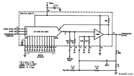
This circuit is similar to that of Fig.6-8, except that the output is bipolar -VREF to + VREF. (View)
View full Circuit Diagram | Comments | Reading(513)
High_stability_thermocouple_amplifier
Published:2009/7/22 22:40:00 Author:Jessie
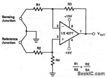
Notice that the reference-junction output is applied to the noninverting input of the 4277, and the sensing-junction output is applied to the inverting input. (View)
View full Circuit Diagram | Comments | Reading(0)
LIGHT_BEAM_RECEIVER
Published:2009/7/6 6:12:00 Author:May

Converts amplitude-modulated light beam back to audio signal for driving transistor radio earphone having resistance of 500-1000 ohms. Miniature 8-ohm loud-speaker can be used by adding output trans-former such as Radio Shack 273-1380. Gain of opamp is controlled by R3, which can be trimmer resistor or pot. Designed for use with transmitter providing amplitude modulation of LED, for short-range voice communication.-F. M. Mims, Optoelectronic Projects, Vol. 1, Radio Shack, Fort Worth, TX, 1977, 2nd Ed., p 44-54. (View)
View full Circuit Diagram | Comments | Reading(1205)
MODULATED_LIGHT_RECEIVER
Published:2009/7/6 6:12:00 Author:May

Two FET stages amplify chopped or smoothly modulated output signal of 5-lm/ft2 light beam, Circuit will produce 1 VRMS at output when R4 is set for maximum gain. Can be used for light-beam communication and for alarm systems.-R.P. Turner, “FET Circuits,” Howard W. Sams, Indianapolis, In, 1977, 2nd Ed., p 113-114. (View)
View full Circuit Diagram | Comments | Reading(0)
AUDIBLE_LIGHT_METER
Published:2009/7/6 6:11:00 Author:May

Low light on cadmium sulfide photocell (Radio Shack 276-116) produces series of clicks in miniature 8-ohm loudspeaker. As light increases, clicks merge into audio tone that increases in frequency as light intensity increases. Can be used for classroom demonstrations or as sunrise alarm clock. Circuit is quiet in total darkness.-F. M. Mims, Optoelectronic Projects, Vol. 1, Radio Shack, Fort Worth, TX, 1977, 2nd Ed., p 61-66. (View)
View full Circuit Diagram | Comments | Reading(1702)
LIGHT_CHANGE_SENSOR_DRIVES_RELAY
Published:2009/7/6 6:10:00 Author:May
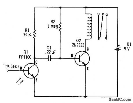
Capacitive coupling between phototransistor and bipolar transistor makes circuit respond only to interruptions or rapid changes in light while ignoring normal gradual changes in ambient light as caused by clouds or at sunrise. Relay pulls in when flash of light occurs and drops out when light is removed, Use Radio Shack 275-004 miniature relay.-F. M. Mims, Transistor Projects, Vol. 3, Radio Shack, Fort Worth, TX, 1975, p 69-74. (View)
View full Circuit Diagram | Comments | Reading(1767)
LIGHT_CHANGE_DETECTOR
Published:2009/7/6 6:10:00 Author:May

Combination amplifier and detector using 3140 opamp responds only to sudden changes in light on photocell while ignoring slow changes in ambient light. When beam is suddenly broken, opamp output swings positive and stays positive for delay time set by recharging of 0.05-μF capacitor on positive input. Delay locks out spurious signals until photocell resets itself to normal illumination. Values shown give time-out delay of about 1 s, with clean conditioned rectangular output pulse.-D. Lancaster, CMOS Cookbook, Howard W. Sams, Indianapolis, IN, 1977, p 346-347. (View)
View full Circuit Diagram | Comments | Reading(771)
GARAGE_LIGHT_CONTROL
Published:2009/7/6 6:09:00 Author:May
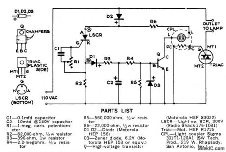
When mounted on far wall in garage, controller picks up head-light beams as car is driven in at night and turns light. on one or more garage lights long enough (3 min) for driver to get out of car and reach exit. Controller then flickers lights as warning and begins dimming them out. With parts specified, will handle up to 800 W of lamps. Adjust sensitivity control R1 so lighe in optocoupler CPL comes on when headlights strike light-operated SCR. Controller must be kept out of direct sunlight. For manual control, connect, connect pushbutton switch between points A and B. To increase time delay, increase value of C2. With 20μF, time will be doubled.-C. R. Lewart, Automatic Garage Light Control, Popular Science, July 1973, p 110. (View)
View full Circuit Diagram | Comments | Reading(808)
ON_OFF_CONTROL
Published:2009/7/6 6:08:00 Author:May

RCA CA3062 combination photodetector and power amplifier provides ON/OFF output in response to light signal. Out-put transistors in IC should be either saturated or blocked to avoid heat rise in silicon chip. Complementary outputs give choice of load normally on or normally off when light from infrared emitter falls on photo input of IC. Interruption of light path then produces opposite load condition - Linear Integrated Circuits and MOS/FET’s, RCA Solid State Division, Somerville, NJ, 1977, p 156. (View)
View full Circuit Diagram | Comments | Reading(922)
PHOTOTRANSISTOR_RELAY
Published:2009/7/6 6:07:00 Author:May
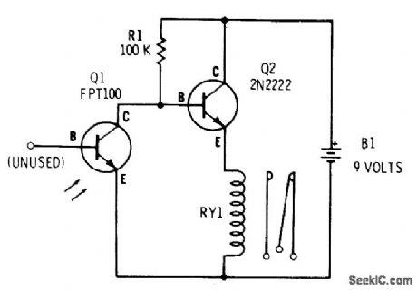
With phototransistor Q1 dark, R1 biases Q2 into conduction and miniature SPDT relay (Radio Shack 275-004) is energized. When light falls on Q1, Q2 is turned off and relay drops out. Battery drain is about 5 mA in darkness, dropping almost to 0 mA with light.-F. M. Mims, Transistor Projects, Vol. 3, Radio Shack, Fort Worth, TX, 1975, p 69-74. (View)
View full Circuit Diagram | Comments | Reading(2682)
AUDIBLE_LIGHT_SENSOR
Published:2009/7/6 6:07:00 Author:May

741 opamp is connected as audio oscillator with Radio Shack 276-677 photocells in feedback circuits. When light strikes PC1, its resistance decreases and frequency of audio tone in headphone decreases correspondingly. When light strikes PC2, which is connected to noninverting input of 741, increase in illumination serves to increase frequency. Choose R4 to reduce volume to desired level. R3 is balancing control for photocells.-F. M. Mims, Integrated Circuit Projects, Vol. 2, Radio Shack, Fort Worth, TX, 1977, 2nd Ed., p 81-86. (View)
View full Circuit Diagram | Comments | Reading(1781)
PUNCHED_TAPE_READER
Published:2009/7/6 6:06:00 Author:May
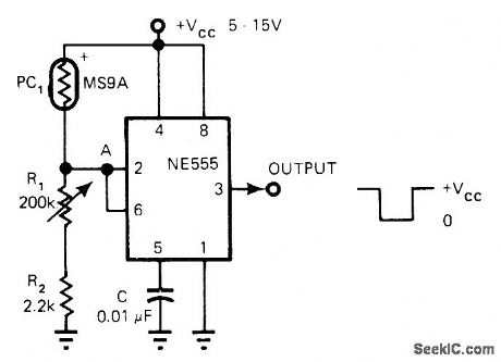
Connection of 555 timer as Schmitt trigger produces output pulses with sharp rise and fall times that are independent of tape speed. Output is compatible with TTL or CMOS circuits. When scanning light beam hits hole in punched card or tape, resistance of light-sensitive resistor drops sharply and voltage at pins 2 and 6 rises above 0.67 VCC. Voltage at output pin 3 then drops sharply from VCC to 0 V. When PC1 goes dark, circuit switches rapidly back to original state. Reverse PC1 and R1-R2 for positive edge-triggered logic.-S. Sarpangal, 555 Timer Implements Tape Reader, EDN Magazine, Jan. 5, 1978, p 86 and 90. (View)
View full Circuit Diagram | Comments | Reading(1738)
5_kHz_PHOTOCELL_OSCILLATOR
Published:2009/7/6 6:04:00 Author:May
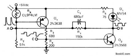
Provides 5-V pulses at about 5 kHz only if photocell is illuminated by its companion LED. Repetition rate varies with illumination, so interruption or attenuation of light produces easily detected frequency change that can be used as control signal. Applications include fail-safe interruption monitor and illumination transducer. Oscillation stops if beam is completely interrupted or if strong ambient light falls on photocell.-H. L. Hardy, FM Pulsed Photocell Is Foolproof, EDN Magazine, March 5, 1975, p 72. (View)
View full Circuit Diagram | Comments | Reading(703)
RATIO_OF_TWO_UNKNOWNS
Published:2009/7/6 6:03:00 Author:May
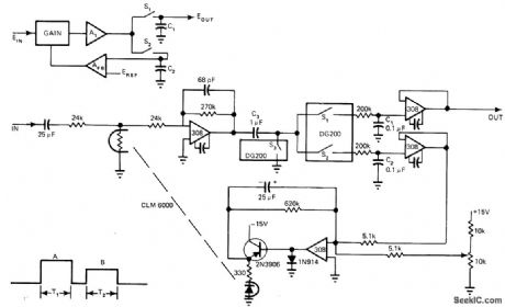
Developed for use when two signals are time-shared on same input line, such as exists when two LEDs alternately illuminate single photocell. Measures ratio of amplitudes of unknowns with accuracy better than 1%. During time period T1, input is sampled through s2 and stored on C2 for comparison with reference voltage Result is applied through switch able amplifier network AFB to gain control element which is LED-photoresistor coupled pair (CLM 6000) This closed loop adjusts signal gain to make denominator of ratio equal to reference voltage. Numerator, corresponding to time T2, is multiplied by-same gain so numerator output is proportional to de-sired ratio B/A of unknowns. Article describes circuit operation in detail.-R. E. Bober, Here's a Low-Cost Way to Measure Ratios, EDN Magazine, March 5, 1976, p 108, 110, and 112. (View)
View full Circuit Diagram | Comments | Reading(525)
SOUND_EFFECTS_GENERATOR_1
Published:2009/7/6 6:03:00 Author:May

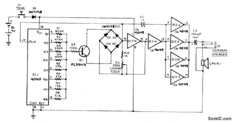
This circuit can generate a European police-car slren,bird nolses,spaceship sounds,etc.In addition,it can be put to use as a doorbell,an alarrm,etc.The circuit consists of four parts:a binary counter,a D/A converter,a VCO,and an audio output amplifier.The initial frequency of oscillation IS determined by potentiometer R11.The VCO firstoscillates at a relatively low frequency,and gradually picks up speed as the control voltage supplied by the D/A converter mcreases.The D/A converter IS the group of resistorsR1-R8.When none of IC1's outputs IS active,little current will flow into the base of Q1,so the VCO's control voltage will be low.As more and more counter outputs becomeactive,base current mcreases,and thereby so does the VCO's frequency of oscillation.The VCO itself IS composed of IC2-a,IC2-b,Q1,and the timing network comprising D1-D4,C1,R10,and R11.The buffer amplifier is made up of the four remammg gatesfrom IC2,all wired In parallel.
(View)
View full Circuit Diagram | Comments | Reading(1334)
| Pages:1040/2234 At 2010211022102310241025102610271028102910301031103210331034103510361037103810391040Under 20 |
Circuit Categories
power supply circuit
Amplifier Circuit
Basic Circuit
LED and Light Circuit
Sensor Circuit
Signal Processing
Electrical Equipment Circuit
Control Circuit
Remote Control Circuit
A/D-D/A Converter Circuit
Audio Circuit
Measuring and Test Circuit
Communication Circuit
Computer-Related Circuit
555 Circuit
Automotive Circuit
Repairing Circuit