
Circuit Diagram
Index 1036
POWER_BOOSTER_2
Published:2009/7/6 7:07:00 Author:May
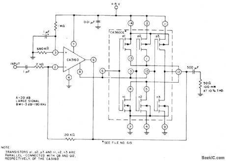
CA3600E CMOS transistor array provides parallel-connected transistors for power-boosting capability with CA3160 opamp. Feedback is used to establish closed. loop gain of 20 dB, Typical large-signal band-width (-3 dB) is 190 kHz, - Linear Integrated Circuits and MOS/FET 's, RCA Solid State Division, Somerville, NJ, 1977, p 271-273. (View)
View full Circuit Diagram | Comments | Reading(719)
TWANG_TWANG_CIRCUIT
Published:2009/7/6 7:07:00 Author:May
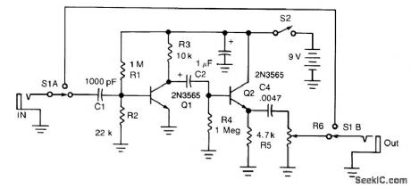
Twang is a guitar sound that more or less approximates a banjo or mandolin. The circuit produces unusual sounds from an ordinary electric guitar by cutting the bass, severely distorting the midband and highs, and then amplifying the distortion. S1 cuts the effect in and out, S2 turns the unit on and off.
(View)
View full Circuit Diagram | Comments | Reading(779)
1000_GAIN_AT_2_kHz
Published:2009/7/6 7:06:00 Author:May
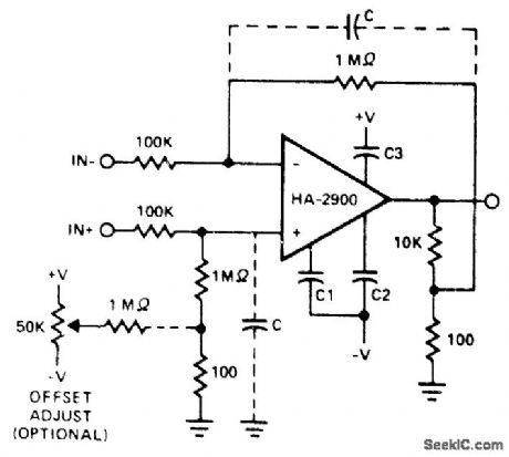
Uses Harris HA-2900 chopper-stabilized opamp. Either input terminal may be grounded, giving choice of inverting or noninverting operation, or inputs may be driven differentially. Symmetrical input networks eliminate chopper noise, limiting total input noise to about 30μ VRMS when C is 0. Noise can be further reduced, at expense of bandwidth, by adding optional capacitors C as shown. Without these capacitors, bandwidth is 2 kHz.- Linear & Data Acquisition Products, Harris Semiconductor, Melbourne, FL, Vol. 1, 1977, p 7-69 (Application Note 518). (View)
View full Circuit Diagram | Comments | Reading(588)
__AUTODRUM
Published:2009/7/6 7:06:00 Author:May
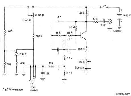
This unit generates a drum-like damped oscillation that sounds best when fed into a higher power amplifier. The beat rate may be determined by operating a foot pedal in much the same manner as for a real drum, or by means of an internal oscillator, the speed of which may be preset.
(View)
View full Circuit Diagram | Comments | Reading(685)
PRECISION_ABSOLUTE_VALUE
Published:2009/7/6 7:05:00 Author:May
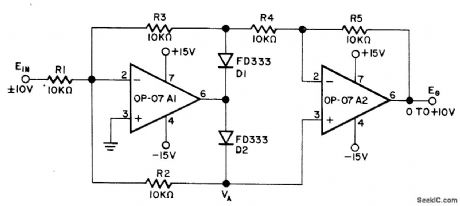
Circuit using two Precision Monolithics OP-07 opamps provides precise full-wave rectification by inverting negative-polarity input voltages and operating as unity-gain buff er for positive-polarity inputs. Applications include positive-peak detectors, single-quadrant multipliers, and magnitude-only measuring systems. For positive inputs, circuit simply operates as two unity-gain amplifier stages. Negative input turns D1 off and D2 on, changing resistor currents precisely enough to give overall circuit gain of -1. Design equations are given.-D. Soderquist and G. Erdi, The OP-07 Ultra-Low Offset Voltage Op Amp-a Bipolar Op Amp That Challenges Choppers, Eliminates Nulling, Precision Monolithics, Santa Clara, CA, 1975, AN-13, p 10. (View)
View full Circuit Diagram | Comments | Reading(3532)
UNUSUAL_FUZZ
Published:2009/7/6 7:05:00 Author:May
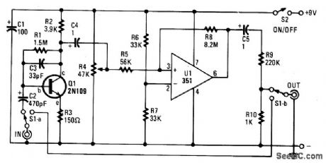
It seems that guitar fuzz boxes have been around since the beginning of rock, and have seen little improvement over the years. This one is somewhat different because rather than simply distorting the sound, it also pulses in step with the peaks of the waveform from the pickup because of the Schmitt trigger op amp circuit. Capacitor C2 requires some explanation. It should normally be a 1- or 2-μF electrolytic capacitor. However, we show the value as 470 pF because it's recommended as an experimental value giving fgr out effects.
(View)
View full Circuit Diagram | Comments | Reading(852)
SUMMING_OPAMP
Published:2009/7/6 7:04:00 Author:May
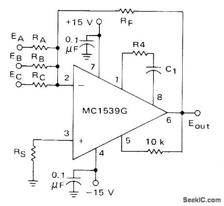
Motorola MC1539 serves as closed-loop summing amplifier having very small loop-gain error because of high open-loop gain. RS should equal parallel combination of RA, RB, RC, and RF.-E. Renschler, The MC1539 Operational Amplifier and Its Applications, Motorola, Phoenix, AZ, 1974, AN-439, p 18. (View)
View full Circuit Diagram | Comments | Reading(689)
WAA_WAA_CIRCUIT
Published:2009/7/6 7:04:00 Author:May

The waa-waa effect is achieved as certain frequencies are amplified more than others.A phase shift RC oscillator makes up the basic circuit. Negative feedback is obtained by feeding part of the signal back to the base. When adjusting initially, RV1 is turned to minimum. RV2 is adjusted to a point at which an audible whistle appears indicating oscillation. RV1 is then adjusted till the oscillation just disappears. It should be possible to set RV2 to any value without any oscillation, this should also be achieved with the minimum possible value of RV1. (View)
View full Circuit Diagram | Comments | Reading(935)
300_Hz_VOLTAGE_FOLLOWER
Published:2009/7/6 7:03:00 Author:May
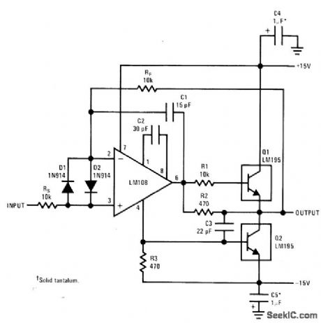
Simpie LM195 power output stage provides 1-A output for voltage-follower connection of LM108 opamp.-R. Dobkin, Fast IC Power Transistor with Thermal Protection, National Semiconductor, Santa Clara, CA, 1974, AN-110, p 6. (View)
View full Circuit Diagram | Comments | Reading(643)
STEAM_LOCOMOTIVE_WHISTLE
Published:2009/7/6 7:02:00 Author:May

The waveform of a steam whistle is a complex combination of white noise and an audio frequency oscillation. The noise generator is a transistor (Q1) biased into zener mode. The audio frequency oscillation is a straightforward mixture of two similar (but not identical) sine waves, which after their addition produce a more complex waveshape.The sine wave generators are twin-t oscillators. Preset RV1 mixes the two sine waves so that an appropriate waveform is obtained. RV2 mixes this waveform with the white noise. Adjustment of all three presets will result in the required sound. Integrated circuit IC1 is an operational amplifier used as a simple mixer/amplifter which combines the steam whistle, chuffer, (generated elsewhere) and two-tone horn sounds into one, suitable for amplification by an extemal amplifier.
(View)
View full Circuit Diagram | Comments | Reading(2870)
VOLTAGE_FREQUENCY_CONVERTER
Published:2009/7/6 7:01:00 Author:May

Uses opamp A1 as integrator and A2 as regenerative comparator with hysteresis, to generate sequence of pulses with repetition frequency proportional to DC input voltage, Article gives design equations and typical waveforms. Input voltage range is 10 mV to 20 V for linear operation.-G. B. Clayton, Experiments with Operational Amplifiers, Wireless World, Dec. 1973, p 582. (View)
View full Circuit Diagram | Comments | Reading(0)
A_D_converter_for_nonratiornetric_transducer_inputs_buffered
Published:2009/7/23 0:43:00 Author:Jessie
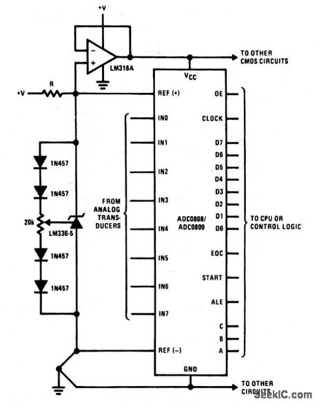
This circuit is similar to that of Fig. 6-17, except that the supply is buffered through an op-amp connected for unity gain. This isolates the ADC reference from the ADC supply (as well as from other system components).
(View)
View full Circuit Diagram | Comments | Reading(466)
PRECISION_RECTIFIER_WITH_GAIN
Published:2009/7/6 7:01:00 Author:May

Gain is selectively added during open-loop switching transition of precision rectifier diodes D1 and D2 in feedback loop of opamp, to boost speed while maintaining feedback stability following switching. Q1 andQ2 add gain of about 250 up to 30 kHz during switching, because D1 and D2 are then off and do not shunt output of added stage. Following transition, one of diodes conducts heavily, shunting high output impedance of stage and dropping its gain below unity. Article covers circuit operation in detail-J.Graeme, Boost Precision Rectifier BW above That of Op Amp Used, EDN Magazine, July 5, 1974,p67-69. (View)
View full Circuit Diagram | Comments | Reading(679)
TESTING_300_KW_UHF_TUBE
Published:2009/7/22 23:58:00 Author:Jessie
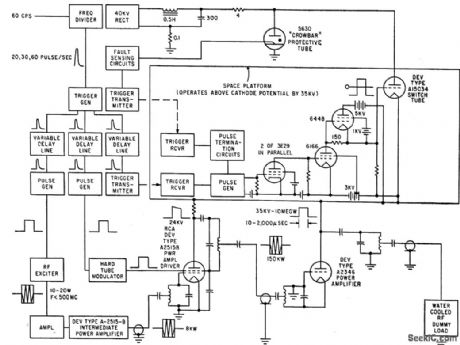
If arc develops in protected A2346 tube, ignitron crowbar circuit grounds power supply in less than 5 microsec. Keying circuits operate at 35-kv plate voltage of tube under lest, applied in pulses 10 to 2,000 microsec wide through switch tube. Peak plate current is almost 300 amp during 5-megcwall output test. -G. Flynn, Super-Power Electron Tube for UHF Band, Electronics, 33:15, p 70-72. (View)
View full Circuit Diagram | Comments | Reading(488)
BIRD_CHIRP
Published:2009/7/6 7:00:00 Author:May
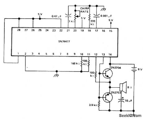
For a barking dog,the capacitor at pin 17 o changed to 15 pF to mcrease the frequency of the VCO.
(View)
View full Circuit Diagram | Comments | Reading(852)
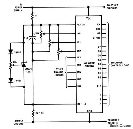
Ratiometric_AID_converter_with_centered_reference_using_resistors
Published:2009/7/22 23:54:00 Author:Jessie

This circuit is similar to that of Fig. 6-13 and 6-15, except that the reference is provided by fixed resistors. Resistors R1 and R2 are selected to provide odd values of reference voltage required by certain transducers (voltages not normally available with adjustable Zeners, such as the LM336). Notice that R3 must be equal to R1, and that both -VREF and +VREF are applied to the ADC through op amps connected for unity gain. (View)
View full Circuit Diagram | Comments | Reading(489)
QUARTZ_OVERIONE_CRYSTAL_CHECKER
Published:2009/7/22 23:50:00 Author:Jessie

Rapidly measures equivalent parameters, in range of 75 to 200 Mc, by combining active and passive measuring systems. Crystal being measured controls frequency stabiltiy of oscillatory circuit of crystal impedance meter. -D. W. Robertson, Plug-in Bridge Checks VHF Quartz Crystals, Electronics, 3H9, p 82-85. (View)
View full Circuit Diagram | Comments | Reading(809)
Ratiometric_A_D_converter_with_mid_supply_centered_reference
Published:2009/7/22 23:46:00 Author:Jessie
This circuit is similar to that of Fig. 6-13, except that the reference is provided by an LM336 (2.5 V). R1 and R2 should be chosen so that they limit current through the LM336 to about 5 mA, and should track each other over temperature. (View)
View full Circuit Diagram | Comments | Reading(668)
METER_CALIBRATING_POWER_SUPPLY
Published:2009/7/22 23:45:00 Author:Jessie
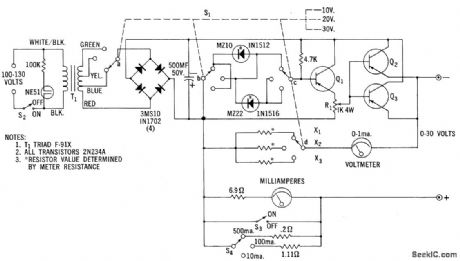
Provides adjustable regulated voltage up to 30 v. Zener diode regulation gives immunity to line voltage variations, giving performance equivalent to that of battery bias packs. Can also be used for testing transistors.- Zener Diode Handbook, International Rectifier Corp., 1960, p 61.
(View)
View full Circuit Diagram | Comments | Reading(1017)
DIELECTRIC
Published:2009/7/22 23:08:00 Author:Jessie
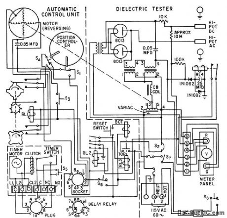
Automatic sequencing of test functions minimizes high-voltage danger to operator and improves accuracy of readings. Control system maybe inserted in any commercial high-pot tester. -F. J. Clounie, P. M. Degroat, and E. M. Szymanski, Control Makes Test Safe, Accurate, Electronics, 33:19, p 88-91. (View)
View full Circuit Diagram | Comments | Reading(800)
| Pages:1036/2234 At 2010211022102310241025102610271028102910301031103210331034103510361037103810391040Under 20 |
Circuit Categories
power supply circuit
Amplifier Circuit
Basic Circuit
LED and Light Circuit
Sensor Circuit
Signal Processing
Electrical Equipment Circuit
Control Circuit
Remote Control Circuit
A/D-D/A Converter Circuit
Audio Circuit
Measuring and Test Circuit
Communication Circuit
Computer-Related Circuit
555 Circuit
Automotive Circuit
Repairing Circuit