
Circuit Diagram
Index 1033
UJT_TD_GARAGE_DOOR_CONTROL_TRANSMIT_TER
Published:2009/7/22 21:23:00 Author:Jessie
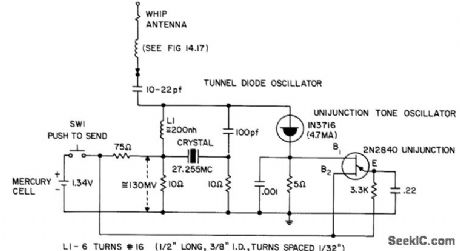
Unijunction tone oscillator modulates 27.255-Mc crystal-controlled tunnel-diode oscillator. Has adequate range for remote control of toys, window displays, garage doors, etc. When voice-modulated, can be used for short-range communication, as in shopping centers and bowling alleys, - Transistor Manual, Seventh Edition, General Electric Co., 1964, p 355.
(View)
View full Circuit Diagram | Comments | Reading(2702)
Light_operated_alarm_with_sensitive_gate_SCR
Published:2009/7/22 21:23:00 Author:Jessie
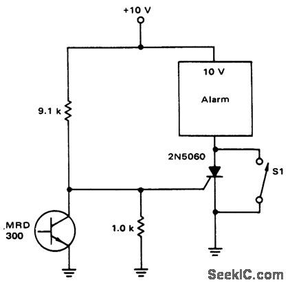
This circuit is similar to that of Fig. 9-41, except that the relay is omitted and a sensitive-gate SCR is used. (View)
View full Circuit Diagram | Comments | Reading(644)
POLARITY_SENSING_ON_OFF_CONTROL
Published:2009/7/22 21:21:00 Author:Jessie
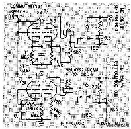
Remote switching circuits are sensitive to positive and negative inputs, thereby doubling number of control channels available from commutating switches of remote control sys tem for robot that performs jobs in danger ous radioactive areas. All functions requiring independent operation are connected to positive input circuits only.-D. A Campbell, Multiplex Circuits for Control of a Robot, Electronics, 33:4, p 46-48. (View)
View full Circuit Diagram | Comments | Reading(901)
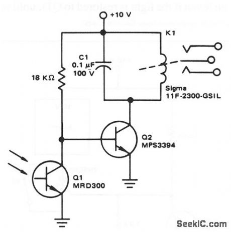
Light_operated_alarm
Published:2009/7/22 21:20:00 Author:Jessie
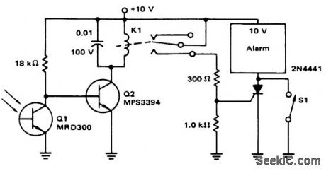
This circuit shows an MRD300 phototransistor that is used to control an alarm (bell, buzzer, etc.). The alarm is turned on when light is removed from Q1. The alarm remains on (even if the light is restored to Q1 ), until momentary-contact switch S1 is closed. (View)
View full Circuit Diagram | Comments | Reading(693)
RECTANGULAR_WAVEFORM_GENERATOR
Published:2009/7/22 21:17:00 Author:Jessie
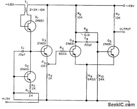
Povides variable frequency and symmetry without interaction of functions. Supply voltage can be -15 to -45 V. Frequency range is variable from 60 cps to 7 kc. Con be used to modulate small transmitter for remote control purposes.-L. E. Spadt, Rectangular Wove. form Generator, EEE, 10:6, p 33-34. (View)
View full Circuit Diagram | Comments | Reading(902)
12_bit_A_D_converter_switched_cotpacitor
Published:2009/7/22 21:15:00 Author:Jessie
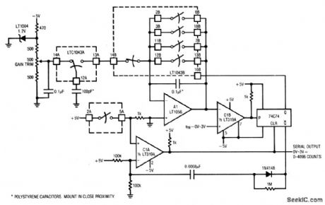
This circuit uses an LTC1043 switched-capacitor to form an economical 12-bit A/D converter. The circuit is self-clocking, has a serial output, and completes a full-scale conversion in 25 ms. Full-scale drift is about 220 ppm/20°C, allowing the circuit to hold 12-bit accuracy over 25°C + 10°C. To calibrate, apply 3 V at the input (non-inverting input of C1B), and trim the gain pot for 4096 pulses output, between data-stream gaps. (View)
View full Circuit Diagram | Comments | Reading(521)
Stereo_magnetic_phono_preamp_and_tone_controls
Published:2009/7/22 21:15:00 Author:Jessie

This circuit requires only 0.1 second for turn-on, Compare to Fig. 1-29.When recording, the frequency response is the complement of the NAB playback equalization, making the composite record and playback response flat (Fig.1 -30B). (View)
View full Circuit Diagram | Comments | Reading(1410)
Counter Circuit of SN7490
Published:2011/7/24 8:37:00 Author:Michel | Keyword: Counter Circuit
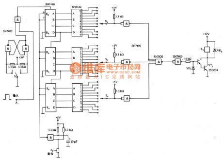
Picture 1 is counter circuit of SN7490.It is accumulating counting circuit of the pulse added to A port.Usually,it is used in counting of input pulse.S4一S6 are reset switches used in counting setting.The corresponding relay controls relative circuit action.If the time pulse shown as picture 1 is connected to A terminal and it can also constitute digital timing circuit which uses power supply frequency as benchmark.
Picture 1:Counter Circuit of SN7490 (View)
View full Circuit Diagram | Comments | Reading(1911)
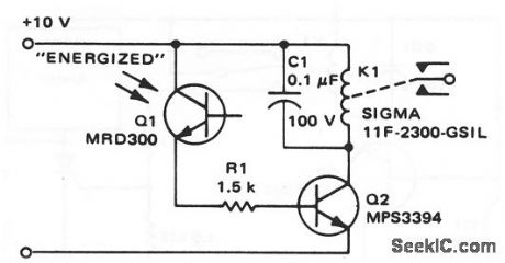
Light_deenergized_relay
Published:2009/7/22 21:07:00 Author:Jessie
This circuit shows an MRD300 phototransistor that is used to control a relay, where the relay is deenergized when light is applied to Q1. (View)
View full Circuit Diagram | Comments | Reading(890)
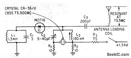
27255_MC_CONTROL_TRANSMITTER
Published:2009/7/22 21:05:00 Author:Jessie
Free-running multivibrator keys power amplifier Q4 at audio role. Range is about 1 mile C6 tunes collector of oscillator to crystal frequency.-Texas lnstruments Inc., Transistor Circuit Design, McGraw-Hill, N.Y., 1963, p 361. (View)
View full Circuit Diagram | Comments | Reading(967)
2_kHz_TWO_PHASE
Published:2009/7/6 7:56:00 Author:May
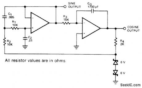
Dual opamp circuit uses two-pole Butterworth bandpass filter followed by phase-shifting single-pole stage that is fed back through zener voltage limiter. Circuit pro-vides simultaneous sine and cosine outputs. Distortion is about 1.5% for sine output and about 3% for cosine. Component values shown are for 741 opamp. For higher frequencies, use 531 opamps to reduce distortion due to slew limiting.- Signetics Analog Data Manual, Signetics, Sunnyvale, CA, 1977, p 642-644. (View)
View full Circuit Diagram | Comments | Reading(1020)
30_kHz_BANDWIDTH
Published:2009/7/6 7:55:00 Author:May
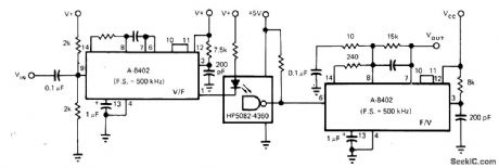
Isolation amplifer circuit uses Intech/Function Modules A-8402 voltage-to-frequency converter having linearity of ±05% to convert input voltage to proportional frequency up to 500 kHz for driving LED of optoisolator. Similar IC converts output of optoisolator back to proportional DC voltage. Supply for conveners is nominally 12 V, but can be 5 to 18 V.-P. Pinter and D. Timm, Voltage-to-Frequency Converters-IC Versions Perform Accurate Data Conversion (and Much More) at Low cost, EDN Magazine, Sept 5, 1977, p 153-157. (View)
View full Circuit Diagram | Comments | Reading(632)
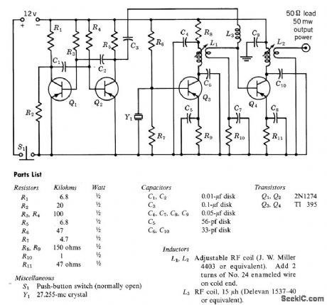
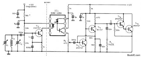
735_MC_CRYSTAL_CONTROLLED_TUNNEL_DIODE_TRANSMITTER
Published:2009/7/22 21:04:00 Author:Jessie
Self-modulated low-power oscillator for remote-controlled toys, trains, and garage doors can also be voice-modulated. Range is about 200 yards, and battery drain is 18 ma.-E. Gottlieb and J.Giorgis, Tunnel Diodes-Using Them as Sinusoidal Generators, Electronics, 36:24, p 36-42. (View)
View full Circuit Diagram | Comments | Reading(956)
BUILT_IN_HYSTERESIS
Published:2009/7/6 7:54:00 Author:May
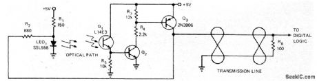
Will operate at all speeds in range from 20 kHz down to zero while still having suitable rise times for driving digital logic. When optical path is blocked, all three transistors are off and output is low. As light on Q1 increases, Q2 and Q3 begin turning on; rising collector of Q3 adds more current through R2 to LED, giving Q1 more light and driving Q1 into saturation. When light dims, Q2 begins to turn off and extra current is cut off, driving Q3 off. With this hysteresis action, there is no constant light level at which circuit will oscillate.-D. C. Hoffman, Optical Sensor Has Built-In Hysteresis, EDN Magazine, June 5, 1973, p 91. (View)
View full Circuit Diagram | Comments | Reading(538)
HUM_BLOCKING_OPTOISOLATOR
Published:2009/7/6 7:52:00 Author:May
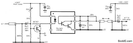
Optoelectronic isolator for audio feed in TV set prevents circulation of ground currents at line frequency, for protection of low-level signal runs from hum interference. Used in tuner providing quality sound and video outputs, circuits for which are given in four-part article. Optoisolator uses light-sensitive Darlington pair in conjunction with infrared-emitting diode. Diode current is adjusted with 50K variable resistor to give best compromise between noise and distortion.-D. C, Read, Television Tuner Design, Wireless World, Jan. 1976, p 51-57. (View)
View full Circuit Diagram | Comments | Reading(717)
LINE_CURRENT_IV_CONTROL_RECEIVER
Published:2009/7/22 21:03:00 Author:Jessie
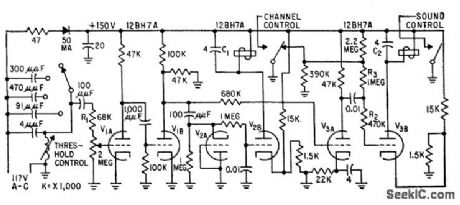
Can be considered as two separate receivers, one detecting unmodulated power-line carrier for channel selection, the other detecting hoth modulated and unmodulated carriers for sound-muting relay. Four individually tuned frequencies (52.5, 57.5, 67.5, und 73.5 kc) ate selectable by switching additional capacitors across that for highest frequency.-J. R. Banker and C. H. Wood, Jr., Line Current Controls Remote Tv Receiver, Electronics, 31:33, p 68-69. (View)
View full Circuit Diagram | Comments | Reading(935)
1500_V_ISOLATION_FOR_DAC
Published:2009/7/6 7:51:00 Author:May

Motorola 4N27 optoisolator provides required isolation between DAC of programmable power supply and remotely located CMOS MC14010 noninverting buffer.-D. Aldridge and N. Wellenstein, Designing Digitally-Controlled Power Supplies, Motorola, Phoenix, AZ, 1975, AN-703, p 9. (View)
View full Circuit Diagram | Comments | Reading(1181)
Light_operated_relay
Published:2009/7/22 21:02:00 Author:Jessie
This circuit shows an MRD300 phototransistor that is used to control a relay, where the relay is energized when light is applied to Q1. (View)
View full Circuit Diagram | Comments | Reading(0)
15_57_MHz_OPTICALLY_ISOLATED_VFO
Published:2009/7/6 7:46:00 Author:May
View full Circuit Diagram | Comments | Reading(731)
Engine Computer Plug-and-Socket Terminal and Instruction Circuits of Beijing Cherokee
Published:2011/7/27 8:19:00 Author:Michel | Keyword: Beijing Cherokee, Plug-and-Socket Terminal, Instruction Circuits

Feet 6 number,wire color, the purpose and connection circuit of engine computer plug-and-socket device are shown as the table.
Table: 2.5 L Petrol Injection Engine Computer Plug-and-Socket Terminal Symbols and Instruction
(View)
View full Circuit Diagram | Comments | Reading(1425)
| Pages:1033/2234 At 2010211022102310241025102610271028102910301031103210331034103510361037103810391040Under 20 |
Circuit Categories
power supply circuit
Amplifier Circuit
Basic Circuit
LED and Light Circuit
Sensor Circuit
Signal Processing
Electrical Equipment Circuit
Control Circuit
Remote Control Circuit
A/D-D/A Converter Circuit
Audio Circuit
Measuring and Test Circuit
Communication Circuit
Computer-Related Circuit
555 Circuit
Automotive Circuit
Repairing Circuit