
Circuit Diagram
Index 1030
TTL_Photodetector_fiberoptic_receiver
Published:2009/7/22 4:30:00 Author:Jessie
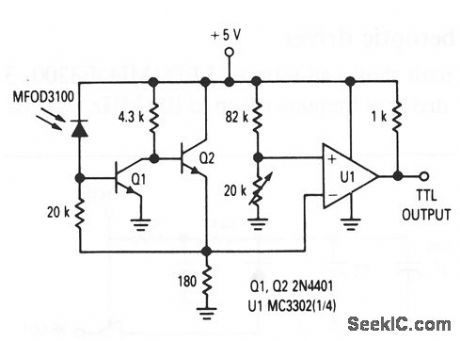
This circuit shows a photo detector (MFOD3100) that is used as a fiberoptic receiver with a TTL output, operating at frequencies up to 1 MHz. (View)
View full Circuit Diagram | Comments | Reading(913)
AC_FLASHER
Published:2009/7/6 8:43:00 Author:May
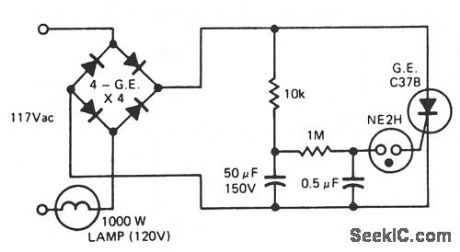
This ac line-operated flasher uses an SCR and is capable of flashing a large lamp. Flashing rate is determined by the 10-KΩ resistor and the 50-mF capacitor. Increasing or decreasing the value of the capacitor has a corresponding effect on the flash rate. (View)
View full Circuit Diagram | Comments | Reading(1312)
Tone_control_with_20_dB_midband_gain
Published:2009/7/22 4:29:00 Author:Jessie

This circuit has boost and cut specifications similar to that of Fig. 1-22.The wideband gain is equal to the ultimate boost or cut, plus one (in this case a gain of 11). For a 20-dB boost and cut, the input loading is essentially equal to the resistance from terminal 3 to ground. (View)
View full Circuit Diagram | Comments | Reading(973)
AUTO_ZEROING_SCALE
Published:2009/7/6 8:43:00 Author:May
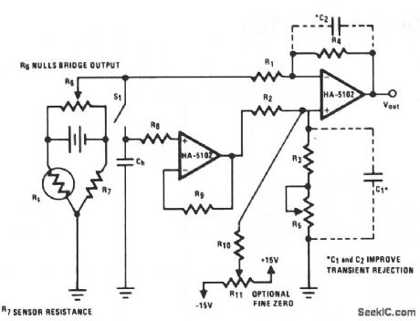
Electronic scales have come into wide use and the HA-510X, as a very low noise device, can improve such designs. This circuit uses a staingauge sensing element as part of a resistive Wienbridge. An auto-zero circuit is also incorporated into this design by including a sample-and-hold network.
The bridge signal drives the inverting input of a differentially configured HA-5102. The noninverting input is driven by the other half of the HA-5102 used as a buffer for the holding capacitor, CH. This second amplifier and its capacitor CH form the sampling circuit used for automatic output zeroing.The 20-KΩ resistor between the holding capacitor CH and the input terminal, reduces the drain from the bias currents. A second resistor RG is used in the feedback loop to balance the effect of R8. If R7 is approximately equal to the resistance of the strain gauge, the input signal from the bridge can be roughly nulled with R6. With very close matching of the ratio R4/R1 to R3/R2, the output offset can be nulled by closing S1. This will charge CH and provide a 0-V difference to the inputs of the second amplifier, which results in a 0-V output. In this manner, the output of the strain gauge can be indirectly zeroed. R10 and potentiometer R11 provide an additional mechanism for fine tuning VOUT, but they can also increase offset voltage away from the zero point. C1 and C2 reduce the circuit's susceptibility to noise and transients. (View)
View full Circuit Diagram | Comments | Reading(603)
ASTABLE_MULTIVIBRATOR
Published:2009/7/6 8:42:00 Author:May

The 4047 is configured as a free-running, asta-ble-multivibrator (oscillator) circuit. That configura-tion, offers three different outputs. The output pulses at theQ andQ output (pins 10 and 11, respectively) are the same as in the previous two circuits. The third output at pin 13 pulses twice as often as the outputs at 10 and 11. So, the circuit can be used to simultaneously provide both positive- and negative-trigger signals since theQ and Q output are never in the same state, and a clock frequency. Thus, the 4047 can replace both a simple oscillator (the 555, for instance) and a flip-flop in some applications. (View)
View full Circuit Diagram | Comments | Reading(0)
TTL_infrared_LED_fiberoptic_driver
Published:2009/7/22 4:28:00 Author:Jessie
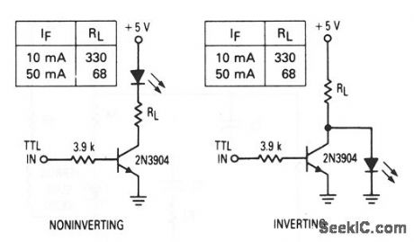
These circuits show an infrared LED (MFOE3200, 3201, 3202) that is used as fiberoptic drivers for both noninverting and inverting TTL inputs. (View)
View full Circuit Diagram | Comments | Reading(1707)
Baxandall_tone_control
Published:2009/7/22 4:28:00 Author:Jessie
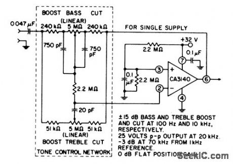
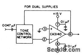
This circuit provides unity gain at midband and uses standard linear potentiometers. Bass/treble, boost, and cut are ±15 dB at 100 Hz and 10 kHz, respectively. Full peak-to-peak output is available up to at least 20 kHz. Amplifier gain is -3 dB down from the flat position (70 kHz). (View)
View full Circuit Diagram | Comments | Reading(0)
100_MHz_frequency_and_2_MHz_ρeriod_counter_using_an_Intersil_ICM7216A_28_pin_DIP
Published:2009/7/22 4:27:00 Author:Jessie
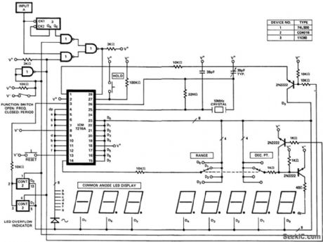
100 MHz frequency and 2 MHz ρeriod counter using an Intersil ICM7216A 28-pin DIP (counesy Intersil, Inc.). (View)
View full Circuit Diagram | Comments | Reading(845)
Photodetector_fiberoptic_receiver
Published:2009/7/22 4:25:00 Author:Jessie
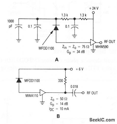
These circuits show a photo detector (MFOD1100) used as a fiberoptic receiver. (View)
View full Circuit Diagram | Comments | Reading(552)
12_W_audio_amplifier_with_discrete_output_and_IC_input
Published:2009/7/22 4:25:00 Author:Jessie

This circuit has a true complementary-symmetry output with a programmable IC amplifier input. (View)
View full Circuit Diagram | Comments | Reading(885)
SCR_RING_COUNTER
Published:2009/7/6 8:40:00 Author:May

One lamp at a time is lit in the string to give the appearance of a moving point of light. (View)
View full Circuit Diagram | Comments | Reading(870)
Infrared_LED_fiberoptic_driver
Published:2009/7/22 4:23:00 Author:Jessie
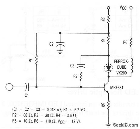
This circuit shows an infrared LED (MFOE3200, 3201, 3202) that is used as a fiberoptic driver at frequencies up to 100 MHz. (View)
View full Circuit Diagram | Comments | Reading(633)
THREE_YEAR_LED_FLASHER
Published:2009/7/6 8:39:00 Author:May

Inserting two 1-MΩ resistors, R1 and R2, in the output stage of one of the circuit's inverters limits the current needed by the oscillator to no more than a few μA. This circuit includes a CD4007 package, which has three CMOS inverters. It forms a standard three-inverter oscillator. Resistors R1 and R2, in series with separate drains on inverter pins 8 and 13, limit the oscillator's supply current. Capacitor C1 and resis-tors R5 set the off time of the oscillator, C1; R6 sets the on time. A VN10KM small-power FET, current-limited by R4, drives two HLMP-3300 LEDs. The LEDs consume about 20 mA for 1 ms. Their average current determines battery life. Since the LEDs in the circuit flash at 1 Hz, the average current drain is about 1/1000 of 20 mA, or 20 μa. A 9-V battery should last about three years at the current drain-essen-tially the shelf life of an alkaline battery. (View)
View full Circuit Diagram | Comments | Reading(1549)
RING_AROUND_LED_FLASHER
Published:2009/7/6 8:35:00 Author:May

When power is first turned on, two of the LEDs are on and the other two remain off until the timing cycle reverses. The LEDs flash in pairs, but by pressing and holding S1 closed until only one of the LEDs is on, and then releasing it, the four LEDs can be made to flash in sequential order. The number of LEDs flashing in a sequential ring can be easily increased to eight by adding another 4001 quad NOR gate. Just repeat the circuit and connect the additional circuit in series with the first-input to output-as an extension of the first circuit. When power is connected to the eight-LED flasher circuit, four LEDs will turn on at once and then flash off as the four remaining LEDs come on. As before, just press S1 and hold closed until all but one LED turns off; then the LEDs will begin their sequential march in a circle. You can connect as many circuits in series as you like. (View)
View full Circuit Diagram | Comments | Reading(984)
Discrete_component_Darlington_audio_amplifier
Published:2009/7/22 4:21:00 Author:Jessie


This circuit provides a 15-, 20-, or 25-W output, depending on the power source and component values (as shown), with overload protection, using Darlingtons in the output stages. Figures 1-20B and 1-20C show the PC-board layout and performance characteristics, respectively. (View)
View full Circuit Diagram | Comments | Reading(2606)
RUMBLE_FILTER_2
Published:2009/7/6 8:33:00 Author:May

View full Circuit Diagram | Comments | Reading(556)
FOURTH_ORDER_CHEBYSHEV_BANDPASS_FILTER
Published:2009/7/6 8:32:00 Author:May

View full Circuit Diagram | Comments | Reading(945)
FOURTH_ORDER_CHEBYSHEV_HIGH_PASS_FILTER
Published:2009/7/6 8:31:00 Author:May

View full Circuit Diagram | Comments | Reading(692)
SIXTH_ORDER_ELLIPTIC_HIGH_PASS_FILTER
Published:2009/7/6 8:30:00 Author:May

View full Circuit Diagram | Comments | Reading(674)
TYPICAL_ACTIVE_BANDPASS_FILTER
Published:2009/7/6 8:27:00 Author:May

View full Circuit Diagram | Comments | Reading(846)
| Pages:1030/2234 At 2010211022102310241025102610271028102910301031103210331034103510361037103810391040Under 20 |
Circuit Categories
power supply circuit
Amplifier Circuit
Basic Circuit
LED and Light Circuit
Sensor Circuit
Signal Processing
Electrical Equipment Circuit
Control Circuit
Remote Control Circuit
A/D-D/A Converter Circuit
Audio Circuit
Measuring and Test Circuit
Communication Circuit
Computer-Related Circuit
555 Circuit
Automotive Circuit
Repairing Circuit