
Circuit Diagram
Index 1032
Ultra_high_gain_audio_amplifier
Published:2009/7/22 20:18:00 Author:Jessie

Sometimes called the JFET μ amp, this circuit provides a very low-power, high-gain amplifying function. Because μ of a JFET increases as drain current decreases, the lower drain current is, the more gain you get. However, dynamic range is sacrificed with increasing gain. (View)
View full Circuit Diagram | Comments | Reading(0)
Magnetic_pickup_phono_preamp
Published:2009/7/22 20:16:00 Author:Jessie


This preamplifier provides proper loading to a reluctance-type phono cartridge. The circuit provides about 25 dB of gain at 1kHz (2.2-mV input for 100-mV output), and features S+ S/N ratio of better than -70 dB (referenced to 10-mV input at 1kHz). The feedback provides for RIAA equalization with a dynamic range of 84 dB (reference to 1kHz). (View)
View full Circuit Diagram | Comments | Reading(1075)
BASIC_MOS_OSCILLATOR
Published:2009/7/6 7:57:00 Author:May
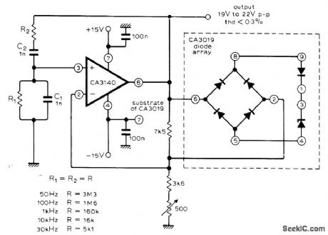
Output is 50 Hz when R1 and R2 are 3.3 megohms, increasing to 30 kHz as resistor values are reduced to 5100 ohms. Circuit has no inherent lower frequency limit; with 22-megohm resistors and 1-μF capacitors for C1 and C2, sine-wave output is 0.007 Hz. Articlegives basic equations for circuit. Features indude high input impedance, fast slew rate, and high output voltage capability. Combination of bridge rectifier with monolithic zener diodes in regulating system provides practically zero temperature coefficient.-M. Bailey, Op-Amp Wien Bridge Oscillator, Wire-less World, Jan. 1977, p 77. (View)
View full Circuit Diagram | Comments | Reading(649)
Video_amplifier_dc_stabilization_summing_point_technique
Published:2009/7/22 7:57:00 Author:Jessie
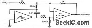
In this circuit, A2 handles high-frequency inputs while A1 stabilizes the dc operating point. The 4.7 k-220-Ω divider at the A2 input prevents excessive drive during start-up. The circuit combines the A135-μV offset and 1.5 V/℃ drift with the A2450 V/μs slew rate and 90-MHz bandwidth. Bias current, dominated by A2, is about 500 nA. (View)
View full Circuit Diagram | Comments | Reading(551)
Loop_through_video_cable_receiver
Published:2009/7/22 7:53:00 Author:Jessie
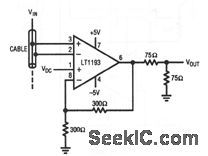
In this circuit, an LT1193 differential amplifier is placed across a distribution cable to extract the video signal. Common-mode signals are rejected by the LT1193 differential inputs. Differential gain and phase errors measure 0.02% and 0.1°, respectively. A separate input permits dc level adjustment. (View)
View full Circuit Diagram | Comments | Reading(574)
Multiplexed_video_amplifier
Published:2009/7/22 6:49:00 Author:Jessie

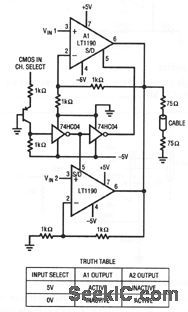

This circuit is a simple way to multiplex two video amplifiers onto a single 75-Ω cable. The appropriate amplifier is activated in accordance with the truth table. Amplifier performance includes 0.02% differential gain error and 0.1' differential phase error. The 75-Ω back termination (looking into the cable) means that the amplifier must swing 2 Vpp to produce 1 Vpp at the cable output. (View)
View full Circuit Diagram | Comments | Reading(510)
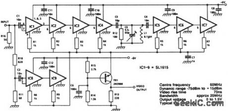
Wideband_log_IF_strip
Published:2009/7/22 6:48:00 Author:Jessie


The SL1615 shown in this figure is a bipolar wideband amplifier for use in successive-detection log IF strips. (View)
View full Circuit Diagram | Comments | Reading(641)
Wideband_log_amplifier
Published:2009/7/22 6:41:00 Author:Jessie
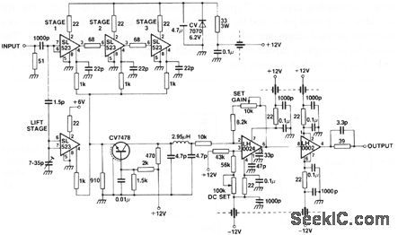


This circuit consists of six log stages (two stages in each dual SL523) and two lift stages, which gives an overall dynamic range of greater than 80 dB. Both the dc level and gain of the video output are adjustable. (View)
View full Circuit Diagram | Comments | Reading(611)
Simple_log_IF_strip
Published:2009/7/22 6:40:00 Author:Jessie
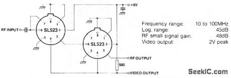


The SL523 shown In this figure is similar to the SL521 shown in Fig.3-2,except that the SL523 is a dual amplifier and provides an approximate 24~dB gain. Typical value for the supply decoupling capacitor is 3 nF. (View)
View full Circuit Diagram | Comments | Reading(696)
Direct_coupled_wideband_log_amplifier
Published:2009/7/22 6:38:00 Author:Jessie


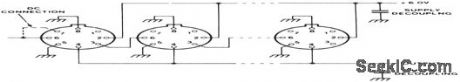
The SL521 shown in this figure is intended primarily for use in successive-detection log IF strips, operating at center frequencies between 10 and 100 MHz. The SL521 is suitable for direct-coupling, and includes a built-in 500-pF supply-decoupling capacitor. Typical stage voltage-gain is 10 to 12 dB. The RF output is taken from pin 4, and the detected output is taken from pin 3. When more than two untuned stages are used, additional decoupling might be required. The values for decoupling capacitors with untuned cascades are: 3 stages 1 nF, 4 stages 3 nF, 5 stages 10 nF, 6 or more stages 30 nF. (View)
View full Circuit Diagram | Comments | Reading(571)
Logarithmic_limiting_amplifier
Published:2009/7/22 6:36:00 Author:Jessie
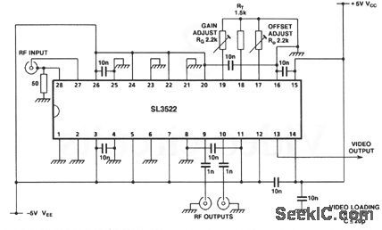
The SL3522 shown in this figure is a 7-stage succes sive-detection log amp for use in the 100- to 600-MHz range. With the values shown, the frequency range is 500 MHz, with a 40-MHz video bandwidth, and a 450-MHz balanced RF bandwidth. Both video gain and offset are adjustable. Gain has an effect on offset, but not vice versa. Typical dynamic range is 75 dB. (View)
View full Circuit Diagram | Comments | Reading(653)
BLOOD_PRESSURE_MONITOR
Published:2009/7/22 6:10:00 Author:Jessie

Continuous indication of blood pressure, with 3% fullscalle accuracy is obtained by mounting variable-reactance pressure transducer in 5-cc syringe inserted directly into patient’s artery Instrument has ranges, for 0-75,0-150,and 0-300mm Hg .Transducer is excited by low-distortion sine wave generated by transistor counterpart of vacuum-tube Wien-bridge oscillator, positive and negative feedback circuits generate 5-kc signal at 1V rms, -O. Z. Roy and J. R. Charbonneau, Transistor Unit Monitors Blood Pressure,Electronic,31:33,p82-83. (View)
View full Circuit Diagram | Comments | Reading(3572)
Darlington_photodetector_fiberoptic_recerver
Published:2009/7/22 6:05:00 Author:Jessie
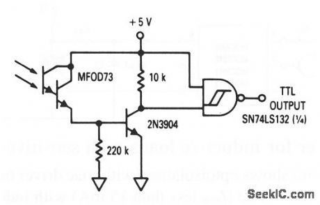
This circuit shows a Darlington photodetector (MFOD73) with a TTL output that operates at frequencies up to 1 kHz. (View)
View full Circuit Diagram | Comments | Reading(677)
Low_power_10_bit_A_D_converter
Published:2009/7/22 21:35:00 Author:Jessie
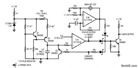
This crystal-controlled integrating A/D converter has a 60-ms conversion time, consumes only 460 μA from a 1.5-V supply, and maintains 10-bit accuracy over a 15°C to 35°C temperature range. To calibrate, apply 0.5000 V to the input and trim the 10-kΩ pot for exactly 1000 pulses out each time the convert-command line is pulsed. No zero trim is required. However, the Q3 inverted 1-mV saturation voltage limits zero resolution to 2 LSBs. (View)
View full Circuit Diagram | Comments | Reading(482)
Strobeflash_slave_adapter
Published:2009/7/22 21:34:00 Author:Jessie
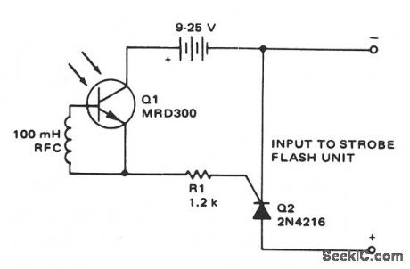
This circuit provides the drive needed to trigger a slave strobeflash, without wires between the master and slave units. When light from the master strobeflash strikes Q1, Q2 is triggered, which applies power to the slave unit. (View)
View full Circuit Diagram | Comments | Reading(593)
Projection_lamp_voltage_regulator
Published:2009/7/22 21:30:00 Author:Jessie
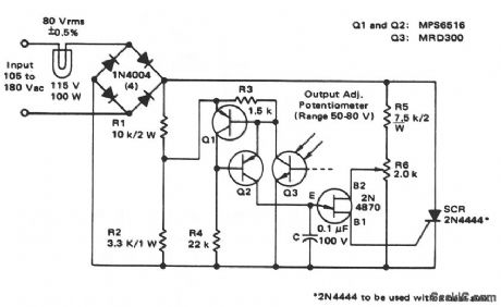
This circuit is similar to that of Fig. 9-18. Here, the magnitude of the charging current that is applied to capacitor C and the position of R6 sot the firing time of the UJT, which, in turn, sets the firing angle of the SCR. Light from the projection lamp sets the current level in Q3, which diverts current from the timing capacitor. R6 sets the desired brightness level by adjusting the UJT firing time. (View)
View full Circuit Diagram | Comments | Reading(0)
Program-controlled Power Supply Circuit of LM101
Published:2011/7/25 10:42:00 Author:Michel | Keyword: Program-controlled, Power Supply Circuit
The picture a and b are program-controlled power supply circuits.A1 and A2 in the circuit are followers work state and its input voltage are voltage drop on R6 or R12.The current flows through R6 or R10 is provided by 1 mA constant current of the constant current source.Picture (a) is +2~+38V positive output voltage and picture (b) is negative output voltage circuit.There is output short-circuit protection circuit in LM101.There is no large current when it is short circuit.C1 or C2 frequency compensates capacitance.The capacitive load is connected to output end and the circuit can work steadily. (View)
View full Circuit Diagram | Comments | Reading(472)
16_bit_A_D_converter_chopper_stabilized
Published:2009/7/22 21:28:00 Author:Jessie
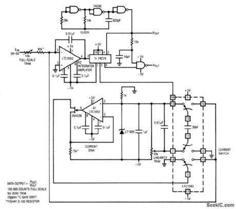
This circuit uses a chopper-stabilized LTC1052 to form a 16-bit A/D converter. To calibrate, apply 5.00000 V and adjust the full-scale trim for 100,000 counts out. Next, set the input to 1.25000 V and adjust the linearity trim for 25,000 counts out. Repeat the procedure until both points are fixed, Converter accuracy is ±1 count with a temperature coefficient of about 15 ppm/°C. (View)
View full Circuit Diagram | Comments | Reading(556)
THREE_TONE_H_F_CONTROLS_TRANSMITTER_
Published:2009/7/22 21:24:00 Author:Jessie
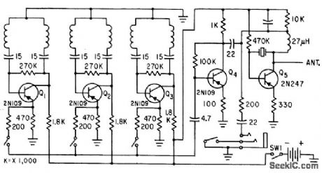
Tone-modulated ground transmitter can be tone-modulated by three different tones, each corresponding to a particular reed of receiving relay and balloon. Consists of three stable audio oscillators (between 200 and 500 cps) and low-power crystal-controlled transmitter in h-f band between 3 and 18 Mc.-R. W. Frykman, Radio Command Set for High. Altitude Balloons, Electronics, 33:35, p 54-55. (View)
View full Circuit Diagram | Comments | Reading(1070)
MILLER_SUPERREGENERATIVE_RECEIVER_
Published:2009/7/22 21:23:00 Author:Jessie
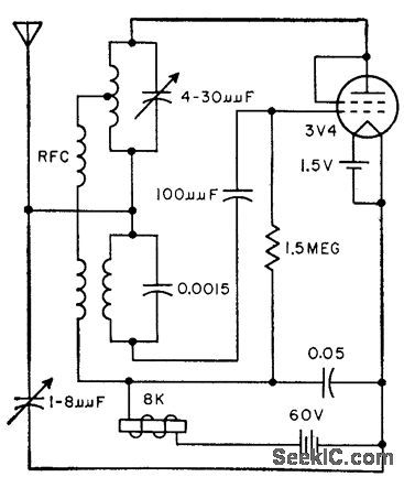
Well-known in model-control field for its reliability. With self-quenching, optimum performance is obtained when receiver is in weak oscillatory slate and incoming signal causes oscillation every third quench cycle. Provides large decrease in plate current when signal arrives.-S. J. Neshyba and F. E. Brooks, Jr., Stable Receiving Circuits for Remote Control, Electronics, 31:31, p 74-76. (View)
View full Circuit Diagram | Comments | Reading(984)
| Pages:1032/2234 At 2010211022102310241025102610271028102910301031103210331034103510361037103810391040Under 20 |
Circuit Categories
power supply circuit
Amplifier Circuit
Basic Circuit
LED and Light Circuit
Sensor Circuit
Signal Processing
Electrical Equipment Circuit
Control Circuit
Remote Control Circuit
A/D-D/A Converter Circuit
Audio Circuit
Measuring and Test Circuit
Communication Circuit
Computer-Related Circuit
555 Circuit
Automotive Circuit
Repairing Circuit