
Circuit Diagram
Index 1031
Optocoupler_driven_SCR
Published:2009/7/22 21:48:00 Author:Jessie
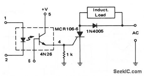
This circuit shows a 4N26 driving an SCR, which, in turn, is used to control an inductive load. The SCR is a sensitive-gate device ( 1 mA of gate current) and the 4N26 has a minimum-current transfer ratio of 0.2, so the 4N26 input current (IF) must be 5 mA. The 1-kΩ resistor prevents the SCR from triggering with small input changes, and the 1N4005 prevents the SCR from triggering with the self-induced voltage when the SCR turns off. (View)
View full Circuit Diagram | Comments | Reading(2961)
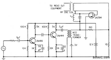
TRANSMITTER_CONTROL_FOR_DRONE
Published:2009/7/22 20:45:00 Author:Jessie
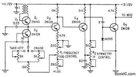
Pulse repetition rate and pulse symmetry control servos that drive rudder and elevator. Pulses modulate transmitter carrier, which is picked up and detected by super regenerative receiver in target drone.-G. B. Herzog, Transistors Simplify Control of Target Drone, Electronics, 32:18, p 52-54. (View)
View full Circuit Diagram | Comments | Reading(3483)
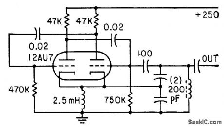
VARIABLE_DE[AY_PULSE
Published:2009/7/22 20:38:00 Author:Jessie
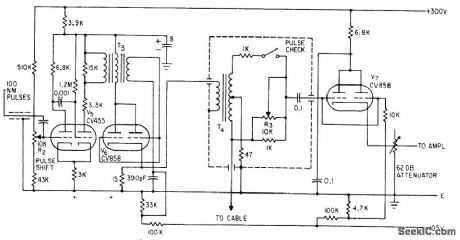
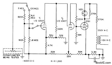
Grid voltage of monostable multivibrator V5 is adjusted by R2 to give delay range of between 171 and 228 microsec, corresponding to 9 to 12 nautical miles of cable under test. Used in pulse echo fault finder to generate transmitted pulse in synchronism with marker pulse generator.-F. Jones and J. H. Reyner, Compact New Instrument Finds Undersea Cable Faults, Electronics, 35:37, p 48-50.
(View)
View full Circuit Diagram | Comments | Reading(621)
STATE_VARIABLE_FILTER_WITH_MULTIPLE_FILTERING_OUTPUTS
Published:2009/7/6 8:26:00 Author:May

View full Circuit Diagram | Comments | Reading(662)
DYNAMIC_NOISE_FILTER
Published:2009/7/6 8:25:00 Author:May

View full Circuit Diagram | Comments | Reading(726)
SCRATCH_FILTER
Published:2009/7/6 8:23:00 Author:May

View full Circuit Diagram | Comments | Reading(0)
EDDY_CURRENT_WIRE_FLAW_DETECTOR
Published:2009/7/22 20:36:00 Author:Jessie
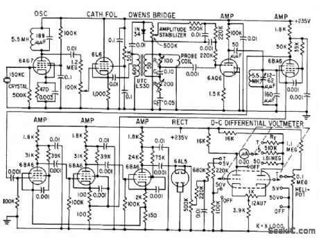
High-sensitivity eddy-current instrument gives me tor indication or permanent record of surface or internal tracts and voids smaller than 0.001 inch in 0.055-inch-diameter zirconium wire used for positioning fuel elements of nuclear reactors. Wire is run through probe coil energized at 150 kc by crystal oscillator, and change in impedance of coil due to law is measured with modified Owens bridge. Output of bridge is amplified in five stages, then rectified for measurement by d-c differential Voltmeter. -R. G. Myers and C. J. Renken, Detecting Invisible Flaws in Wire, Electronics, 31:39, p 72-73. (View)
View full Circuit Diagram | Comments | Reading(1758)
NAB_tape_preamp_with_fast_turn_on
Published:2009/7/22 20:34:00 Author:Jessie

This circuit requires only 0.1 second for turn-on, Compare to Fig. 1-29.When recording, the frequency response is the complement of the NAB playback equalization, making the composite record and playback response flat (Fig.1 -30B). (View)
View full Circuit Diagram | Comments | Reading(954)
INSULATION_RESISTANCE_TESTER
Published:2009/7/22 20:33:00 Author:Jessie
Amplifiers and thyratron give go-no-go indication of insulation resistance. Used in production testing of potentiometer-type pressure-sensing instruments over their operating ranges.-C. N. Boode and C. E. Calohan, Analog Comparator for Production Testing, Electronics, 31:13, p 47-49. (View)
View full Circuit Diagram | Comments | Reading(1907)
TUNNEL_DIODE_CURVE_TRACER
Published:2009/7/22 20:31:00 Author:Jessie
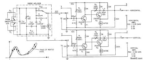
Diode holder uses germanium blocks as low-inductance resistors, for tracing negative-resistance region of tunnel diode. Heating effects may cause double trace.-H. G. Dill and M. It. Mac-Pherson, Tracing Tunnel Diode Curves, Electronics, 33:32, p 62-64.
(View)
View full Circuit Diagram | Comments | Reading(723)
TV_MIXER_TRANSISTOR_TESTER
Published:2009/7/22 20:27:00 Author:Jessie
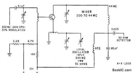
Used as standarized test circuit for mixer transistors in tv and vhf receivers.-G. J. Flynn, Engineering Trends in Consumer Electronics, Electronics, 34:1, p 115-117. (View)
View full Circuit Diagram | Comments | Reading(486)
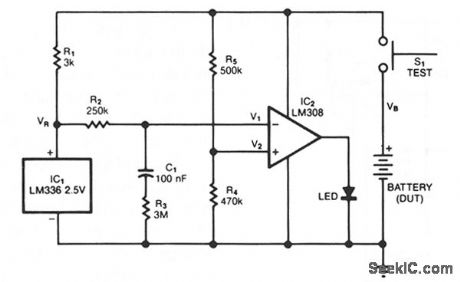
HI_POT_TESTER
Published:2009/7/22 20:24:00 Author:Jessie
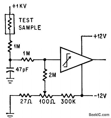
Operational trigger trips when resistance of sample under test is less than 500,000 meg.-P. Lefferts, Operational Trigger For Precise Control, Electronics, 37:28, p 50-55.
(View)
View full Circuit Diagram | Comments | Reading(713)
STATE_VARIABLE_ACTIVE_FILTER
Published:2009/7/6 8:22:00 Author:May

A generalized circuit diagram of the two-pole state-variable active filter is shown. The state-variable filter can be inverting or noninverting and can simultaneously provide three outputs: low-pass, bandpass, and high-pass. A notch filter can be realized by adding one summing op amp.
In the state-variable filter circuit, one amplifier performs a summing function and the other two act as integrators. The choice of passive component values is arbitrary, but must be consistent with the amplifier operating range and input signal characteristics. The values shown for C1, C2, R4, R5, and R6 are arbitrary. Preselecting their values will simplify the filter tuning procedures, but other values can be used if necessary. (View)
View full Circuit Diagram | Comments | Reading(1929)
INDUCTIVE_TELEMETRY_FOR_SPIN_TEST
Published:2009/7/22 20:22:00 Author:Jessie
Transistors in modulated oscillator-transducer package withstand over 6,000 rpm on spin test while radiating measured data inductively from oscillator coils L1-L2 to stationary coil of readout equipment.-H. Baumann, Inductive Telemetry Improves Spin-System Measurements, Electronics, 36:46, p 41-42. (View)
View full Circuit Diagram | Comments | Reading(541)
NOISY_SIGNALS_FILTER
Published:2009/7/6 8:19:00 Author:May

This circuit filters noise, such as glitches and contact bounce, from digital signals. You can easily adjust the circuit for a wide range of noise frequen-cies. The circuit's output changes state only if the input differs from the output long enough for the counter to count eight cycles. If the input changes before the counter reaches its maximum count, the counter resets without clocking the output of flip-flop, IC2. You use R2 to set the frequency of the two-inverter CMOS oscillator, which clocks the counter. Simply adjust the oscillator such that its period is one-eighth that of the noise you want to eliminate. (View)
View full Circuit Diagram | Comments | Reading(663)
SECOND_ORDER_BIQUAD_BANDPASS_FILTER
Published:2009/7/6 8:17:00 Author:May

Note that IQ on each amplifier might be different.AVCL = 10, Q =100,fo=100 Hz. (View)
View full Circuit Diagram | Comments | Reading(614)
VOLTAGE_CONTROLLED_FILTER
Published:2009/7/6 8:13:00 Author:May

The control voltage VC easily sets the cutoff frequency ωo of this state-variable filter to any desired value, from about 1.7 MHz up to 5 MHz, with a BB 204 varicap and R = 100 KΩ. VC can range from 0 to 28 V. This range changes the capacitance of the varicap from about 4 to 12 pF.The circuit consists of input summing circuit A1 and two noninverting integrators, A2 and A3. Both the integrators and the summing-amplifier cir-cuits use CA3450 op amps. With them, cutoff fre-quencies up to 200 MHz are possible.The circuit's cutoff frequency, it's Q-factor, and gain G are simply:
ωo =2/CR, Q =R3/R4, and G = R4/R1
For a given value for R4, say 10 KΩ,Q depends only upon the resistance of R3. TheQ can be any value, even 100, independently of both ωo and G. Similarly, the gain then depends only on the resistance of R1 and can also be set as high as 100. (View)
View full Circuit Diagram | Comments | Reading(0)
TACHOMETER_TESTER
Published:2009/7/22 20:21:00 Author:Jessie
Free-running mvbr, half of which is connected us Colpitts oscillator, gives 1-Mc sine wave, 100% modulated by 15-cps square wave, for testing two-channel tachometer using radioactive sources-R. R. Bockemuehl und P. W. Wood, Unique Two-Channel Tachometer uses Radioisotopes, Electronics, 35:49, p 44-45. (View)
View full Circuit Diagram | Comments | Reading(589)
ELECTRIC_VEHICLE_BATTERY_SAVER
Published:2009/7/6 7:58:00 Author:May

The battery life and operating cost of an electric vehicle is severely affected by overdischarge of the battery .This circuit provides both warning and shutdown.An electronic switch is placed in senes with the propulsion motor contactor coil.Three modes of operation are possible:
· When the propulsion power pack voltageis above the 63-V tnp point,the electronic switch has no effect on operation
·When the propulsion power pack no load voltage IS below 63 V, power will not be supp⒒ed to the propulsion motor since the electronic switch will prevent contactor operation
· When the propulsion power pack loaded voltage drops below 63 V ,the contactor will close and open because of the electronic switch.The bucking operation indicates to the operator need to charge the batteries
(View)
View full Circuit Diagram | Comments | Reading(986)
Typical_tape_playback_amplifier
Published:2009/7/22 20:20:00 Author:Jessie


This circuit requires about 5 seconds to turn on (for the gain and supply voltages shown). The turn-on time is approximately
(View)
View full Circuit Diagram | Comments | Reading(740)
| Pages:1031/2234 At 2010211022102310241025102610271028102910301031103210331034103510361037103810391040Under 20 |
Circuit Categories
power supply circuit
Amplifier Circuit
Basic Circuit
LED and Light Circuit
Sensor Circuit
Signal Processing
Electrical Equipment Circuit
Control Circuit
Remote Control Circuit
A/D-D/A Converter Circuit
Audio Circuit
Measuring and Test Circuit
Communication Circuit
Computer-Related Circuit
555 Circuit
Automotive Circuit
Repairing Circuit