
Circuit Diagram
Index 1049
SINGLE_CHIP_CHECKS_RESISTANCE
Published:2009/7/6 3:44:00 Author:May
Circuit Notes
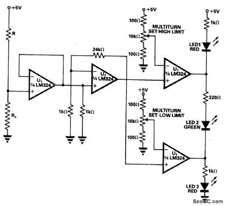
A simple tester can be used for routine checks for resistance on production lines of relays, coils, or similar components where frequent changes in resistance to be tested are not required. The tester is built around a single quad op amp chip, the LM324. R, which is chosen to be around 80 times the resistance to be checked, and the 5 V supply form the current source. The first op amp buffers the voltage generated across the resistance under test, Rx. The second op amp amplifies this voltage. The third and fourth op amps compare the amplified voltage with high and low limits. The high and low limits are segt on multiturn presets with high and low limit resistors connected in place of Rx. LED 1 (red) lights when the resistance is high. LED 2 (greep) shows that the resistance is within limits. LED 3 (red) indicates that the resistance is low. (View)
View full Circuit Diagram | Comments | Reading(567)
SINE_WAVE_SHAPER_
Published:2009/7/6 3:42:00 Author:May

Uses CA3140 opamp as voltage follower, acting with diodes from CA3019 array to convert triangle output of function generator or other source to sine wave having total harmonic distortion typically less than 2%.- Circuit Ideas for RCA Linear ICs, RCA Solid State Division, Somelville, NJ, 1977, p 5. (View)
View full Circuit Diagram | Comments | Reading(1837)
COURTESY_LIGHT_EXTENDER
Published:2009/7/6 3:42:00 Author:May
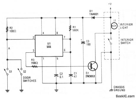
The circuit keeps the courtesy light on for 30 seconds after you close the door. The lead from the door switch is removed and connected to the 555 circuit. The 555 is arranged in a monostable mode, and is triggered by the door switches. The output drives Q1, which is connected across the interior light switch.The interior light is turned on for 30 seconds after the door is opened. If the door(s) are held open for longer than 30 seconds, it will not reset until after the doors are closed. In that case, the lights go out immediately. (View)
View full Circuit Diagram | Comments | Reading(1317)
ELECTRONIC_CAR_HORN
Published:2009/7/6 3:41:00 Author:May
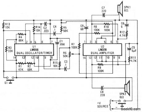
An LM556 dual oscillator/timer, U1, configured as a two-tone oscillator drives U2,a dual 4-watt amplifier. One of the oscillators, pins 1 to 6, contained in U1 produces the upper frequency signal of about 200 Hz, while the second oscillator, pins 8 to 13, provides the lower frequency signal of about 140 Hz. Increase or decrease the frequencies by changing the values of C2 and C3. U1's outputs,pins 9 and 5, are connected to separate potentiometers to provide control over volume and balance. Each half of U2 produces 4 W of audio that is delivered to two 8-Ω loudspeakers via capacitors C7 and C8. (View)
View full Circuit Diagram | Comments | Reading(1291)
MULTIPLYING_D_A_CONVERTER
Published:2009/7/6 3:40:00 Author:May


The circuit performs the function:
VOUT = VIN × N/16
where N IS the binary number from 0 to 15 formed by the digital input If the analog input iS a fixed dc reference,the circuit 15 a conventional 4-bit D to ac signal,in which case the output is the product of the analog signal and the digital signal The circuit on the left is a programmable attenuator with weights of 0,1/4,1/2,or 3/4 The circult on the rightis a noninverUng adder, which adds weights to the first output of 0,1/16,1/8,or 3/16 If four quadrant multiplicatlon is required,place a phase selector circuit in series with either the analog input or output The Do input of that stage becomes the+or-slgn bit of the atgttal input. (View)
View full Circuit Diagram | Comments | Reading(663)
BACK_UP_BEEPER
Published:2009/7/6 3:39:00 Author:May
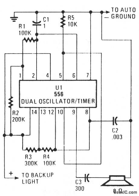
Put the car in reverse and the circuit provides a loud, audible beep at the rate of about one per second (1 Hz). Half of U1, a 556 dual oscillator/timer, is used as a slow-pulse oscillator with a rate of about 1 Hz. Components R2, R1, and C1 form the long time constant. You can calculate on time by t=.7 (R1 + R2) C1 or 1.15 seconds. The off time is shorter than the on time, at.77 second. Enabling pin 4 (reset) is held high to keep the oscillator freerunning when voltage is applied to pin 14. The output at pin 5 is coupled to pin 10 of U1 enabling oscillator 2. Oscillator 2 of U1 produces an audio output of about 1 kHz, as determined by C2, R3, and R4. Pin 10 (reset) of oscillator 2 is connected to the pin 5 output of oscillator 1. So when pin 5 becomes positive, the oscillator beeps a short pulsed tone of 1 kHz. (View)
View full Circuit Diagram | Comments | Reading(631)
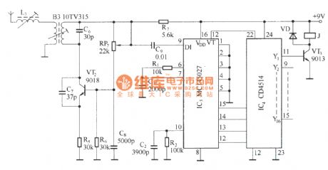
Multi-channel remote control circuit diagram
Published:2011/4/8 3:03:00 Author:Rebekka | Keyword: multi-channel remote control
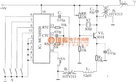
Multi-channel remote control transmitter circuit diagram(MC145026 is a digital encoder):
Multi-channel remote control receiver circuit diagramCD4514BCD is a 4-16 line decoder):
(View)
View full Circuit Diagram | Comments | Reading(3813)
90_W_audio_power_amplifier
Published:2009/7/23 20:36:00 Author:Jessie


This circuit is capable of 90 W into a 4-Ω speaker, or 70 W into an 8-Ω speaker. The circuit features safe area, short-circuit and overload protection, harmonic distortion less than 0.1% at 1.0 kHz, and an all-npn output stage. Figures 1-42B through 1-42E show the circuit performance characteristics. (View)
View full Circuit Diagram | Comments | Reading(963)
AUTOMATIC_HEADLIGHT_DELAY
Published:2009/7/6 3:36:00 Author:May
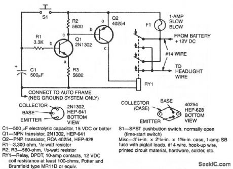
When the driver depresses pushbutton switch S1, timing capacitor C1 charges to 12 V and turns on transistor Q1, which drives power transistor Q2 into conduction. This, in turn, energizes the relay which has its contacts connected in parallel with the headlight switch. The relay will stay energized until C1 discharges to the Q1 turn-off level. The lights-on period is determined by the value of C1, R1, and the charac-teristics of transistor Q1. With values chosen on the schematic, about 60 light-on seconds are provided.
(View)
View full Circuit Diagram | Comments | Reading(620)
Video_coaxial_line_driver
Published:2009/7/23 20:34:00 Author:Jessie
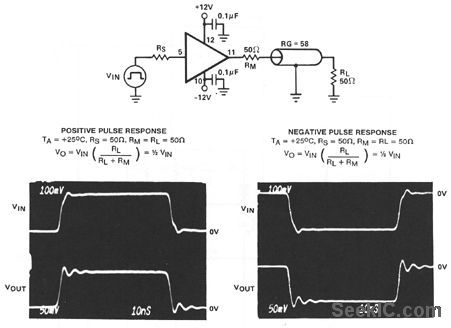
This circuit uses an HA-5033 video buffer as a coax line driver. Notice that both the positive and negative pulse-response waveforms are also shown. The connections given are for the TO-8 metal-can version of the HA-5033.
(View)
View full Circuit Diagram | Comments | Reading(572)
DIRECTIONAL_SIGNALS_MONITOR
Published:2009/7/6 3:33:00 Author:May

A unijunction transistor audio oscillator drives a small speaker. The oscillator's frequency is determined by resistor R2 and capacitor C2. The operating voltage is supplied from the car's turn-signal circuit(s) through D1 and D2. The diodes conduct current from the blinker circuit that is energized, and prevent stray current flow to the other blinker circuit. (View)
View full Circuit Diagram | Comments | Reading(1383)
AUTOMOBILE_VOLTAGE_REGULATOR
Published:2009/7/6 3:32:00 Author:May
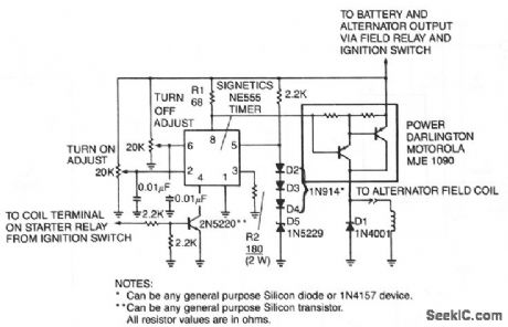
A monolithic 555-type timer is the heart of this simple automobile voltage regulator. When the timer is off so that its output at pln 3 is low,the power Darlington transistor par is off.If battery voltage becomestoo low,less than 14.4 V in this case,the timer turns on and the Darlington par conducts. (View)
View full Circuit Diagram | Comments | Reading(1731)
9_BIT_CMOS_D_A_CONVERTER
Published:2009/7/6 3:30:00 Author:May

Three CD4007A IC packages perform the switch function using a 10-V logic level. A single 15-V supply provides a positive bus for the follower amplifier and feeds the CA3085 voltage regulator. The scale adjust function is prodded by the regulator output control, which is set to a nominal 10 V in this system. The line-voltage regulation (approximately 0.2%) permits 9-bit accuracy to be maintained with a variation of several volts in the supply. System power consumption ranges between 70 and 200 mW; a major portion is dissipated in the load resistor and op amp. The regulated supply provides a maximum current of 440 μA of which 370 μA flows through the scale adjusting. The resistor ladder is composed of 1% tolerance metaloxide film resistors. The ratio match between resistance values is in the order of 2%. The follower amplifier has the offset adjustment nulled at approximately a 1 V output level. (View)
View full Circuit Diagram | Comments | Reading(873)
Stabilized_ultra_wideband_current_mode_feedback_amplifier
Published:2009/7/23 20:32:00 Author:Jessie
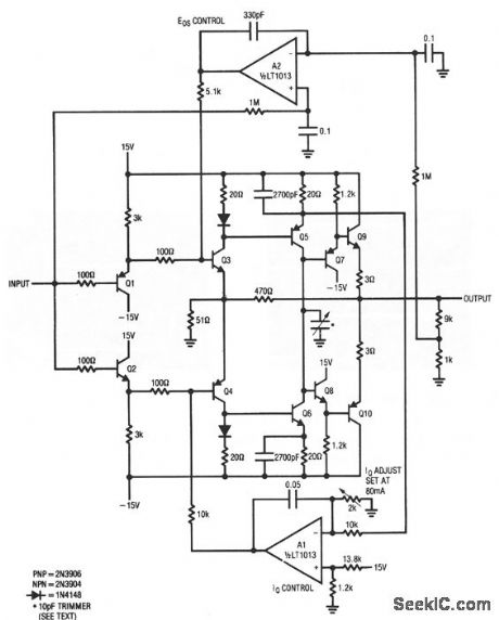
virtually any video or wideband application. For gains from 1 to 20, full-power bandwidth is 25 MHz, with the -3-dB point beyond 110 MHz. Gain is sot for 10 (with the values shown) by the 51- and 470-Ω Q3/Q4 emitter resistors. Slew rate exceeds 3000 V/μs.Damping is optimized with the 10-pF trimmer at the Q5/Q6 collectors. To use the circuit, adjust the IQ level to 80 mA immediately after turn on. Next, sot the A2 input resistor divider to a ratio appropriate to the closed-loop gain (1 and 9 kΩ, in this case). Finally, adjust the 10-pF trimmer for best results (preferably with a square-wave input). Notice that this circuit has no output protection. (View)
View full Circuit Diagram | Comments | Reading(825)
SWITCHED_DIVIDER_FOR_BINARY_COUNTER
Published:2009/7/6 3:29:00 Author:May

Simple circuit provides method of switching division by two into or out of stream of clock pulses. Output is in phase with input and free of spikes. Switching requires only one D-type flip-flop and one inverter. When control is high, logic action gives normal connection for division by two,using D-typeflip-flop; inverterthen restores phase.-J. M. Firth, Control of a Binary Counter for Division by One or Two, Wireless World, Jan. 1975, p 12.
(View)
View full Circuit Diagram | Comments | Reading(975)
Fast_precision_inverter_with_50_V_μs_slcw_rate
Published:2009/7/23 20:30:00 Author:Jessie
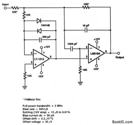
This circuit has a settling time of 12 μs to 0.1% a 10-V step input. (View)
View full Circuit Diagram | Comments | Reading(642)
Video_voltage_follower
Published:2009/7/23 20:28:00 Author:Jessie

This circuit uses an HA-2600 wideband op amp with very high input impedance and low output impedance. The load capacitor is recommended to prevent high-frequency oscillations (possibly from external wiring). Capacitor values up to 100 pF have little effect on bandwidth or glow rate. Figure 3-29B shows an offset adjustment (if required). (View)
View full Circuit Diagram | Comments | Reading(693)
Fast_precision_inverter_with_100_V_μs_slew_rate
Published:2009/7/23 20:28:00 Author:Jessie
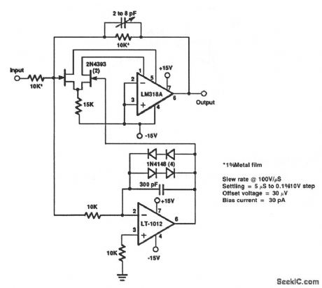
This circuit has a setting time of 5μs to 0.1% with a 10-V step input. (View)
View full Circuit Diagram | Comments | Reading(772)
Composite_video_sync_separator
Published:2009/7/23 20:27:00 Author:Jessie

This circuit uses an HA-2544 video op amp (Fig. 3-29) to separate the TV sync signal from the video and blanking signal with a minimum of external components. (View)
View full Circuit Diagram | Comments | Reading(1419)
75_Ω_differential_input_buffer
Published:2009/7/23 20:25:00 Author:Jessie
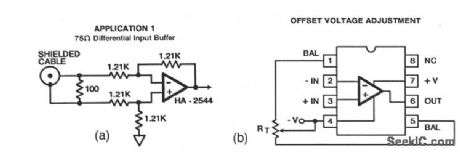
This circuit uses an HA-2544 video op amp to buffer between a 75-Ωline and other video circuits,with a GBW(gain-bandwidth)up to 50MHz.Figure3-29B shows an offset adjustment(if required). A typical range for RT is 20 M. (View)
View full Circuit Diagram | Comments | Reading(575)
| Pages:1049/2234 At 2010411042104310441045104610471048104910501051105210531054105510561057105810591060Under 20 |
Circuit Categories
power supply circuit
Amplifier Circuit
Basic Circuit
LED and Light Circuit
Sensor Circuit
Signal Processing
Electrical Equipment Circuit
Control Circuit
Remote Control Circuit
A/D-D/A Converter Circuit
Audio Circuit
Measuring and Test Circuit
Communication Circuit
Computer-Related Circuit
555 Circuit
Automotive Circuit
Repairing Circuit