Basic Circuit
SINGLE_CHIP_CHECKS_RESISTANCE
Published:2009/7/6 3:44:00 Author:May | From:SeekIC

Circuit Notes
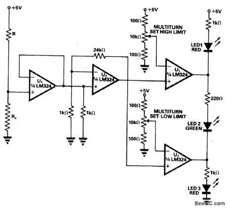
A simple tester can be used for routine checks for resistance on production lines of relays, coils, or similar components where frequent changes in resistance to be tested are not required. The tester is built around a single quad op amp chip, the LM324. R, which is chosen to be around 80 times the resistance to be checked, and the 5 V supply form the current source. The first op amp buffers the voltage generated across the resistance under test, Rx. The second op amp amplifies this voltage. The third and fourth op amps compare the amplified voltage with high and low limits. The high and low limits are segt on multiturn presets with high and low limit resistors connected in place of Rx. LED 1 (red) lights when the resistance is high. LED 2 (greep) shows that the resistance is within limits. LED 3 (red) indicates that the resistance is low.
Reprinted Url Of This Article:
http://www.seekic.com/circuit_diagram/Basic_Circuit/SINGLE_CHIP_CHECKS_RESISTANCE.html
Print this Page | Comments | Reading(3)

Article Categories
power supply circuit
Amplifier Circuit
Basic Circuit
LED and Light Circuit
Sensor Circuit
Signal Processing
Electrical Equipment Circuit
Control Circuit
Remote Control Circuit
A/D-D/A Converter Circuit
Audio Circuit
Measuring and Test Circuit
Communication Circuit
Computer-Related Circuit
555 Circuit
Automotive Circuit
Repairing Circuit
Code: