
Signal Processing
Index 175
(Hitachi) CMT2998 protection circuit
Published:2011/5/29 8:44:00 Author:Christina | Keyword: Hitachi, protection circuit
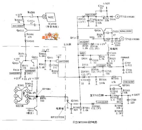
The (Hitachi) CMT2998 protection circuit is as shown in the figure:
(View)
View full Circuit Diagram | Comments | Reading(521)
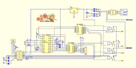
PIC16C54 main control panel of air conditioning circuit
Published:2011/5/28 0:57:00 Author:chopper | Keyword: main control panel, air conditioning
View full Circuit Diagram | Comments | Reading(687)
The 555 multi-functional ceiling fan controller circuit
Published:2011/5/28 21:24:00 Author:Borg | Keyword: multi-functional ceiling fan
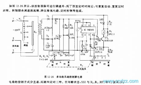
The fan control method is classified into three ways that are direct, interval and timing. In the interval state, 555,R2,R3,RP1,C2,R7,C3 and so on consists a non-steady multi-resonate oscillator, before the charging voltage reaches the trigger LEV(2/3VDD), the 3-pin of 555 is in a high LEV, VT1 is conducting, the relay J pulls in, the fan gets power and starts to run, the running time is determined by R2,R3,RP1 and C2, in the figure, the corresponding time to the parameters is around 25~60s. The interval time means the period after 555 is reset, and C2 discharges(with the help of R7) to the the trigger LEV of 2-pin(1/3VDD), the time span corresponding to the parameter in the figure is about 20s. (View)
View full Circuit Diagram | Comments | Reading(768)
The 555 multi-functional electric control circuit
Published:2011/5/28 21:03:00 Author:Borg | Keyword: multi-functional, electric control
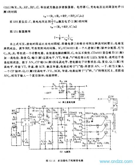
See as the above equations, the discharging time is longer that charging time,i.e the pulling time of relay J is longer than its releasing time, the fan generates gusts. And the intervals of the gusts can be changed by adjusting RP2. IC2(CD4022) is a octal counter/pulse distributor, which consists a counting circuit with C2,R5,R7 and so on. At the moment of power-on, the voltage on C2 doesn't mutate, and the reset terminal(R) (15-pin) of CD4022 is imposed with a high LEV, which lead to the high LEV of Q0 terminal(2-pin), and VT2 is conducting and the indicating LED2 of 0 gear glows green beams that means it is ready to run.
(View)
View full Circuit Diagram | Comments | Reading(459)
The 555 simple natural wind analog control circuit
Published:2011/5/29 22:10:00 Author:Borg | Keyword: natural wind, analog control
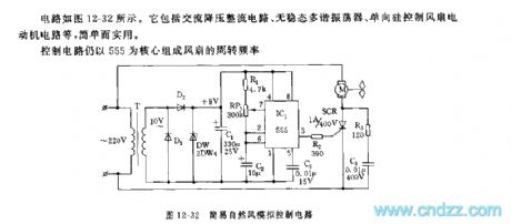
The circuit is as shown in Figure 12-32, which includes the AC step-down rectifier circuit, non-steady multi-resonate oscillator and the motor circuit of single-way silicon control fans, etc. It is simple and practical.
The control circuit is based on 555, and the rotating frequency of the fan is fc=1.44/(R1+PR1)C2, which is about 0.5~30Hz, by adjusting RP1, we can change the time parameters of charging and discharging, so the rotating speed of the fan can be changed, i.e the strength of the wind can be controlled. When the rotating speed is low, the wind is like a breeze. In the figure, R3,C4 and SCR connect in a parallel way, which is used to protect the controllable silicon SCR. (View)
View full Circuit Diagram | Comments | Reading(660)
The 555 discontinuous running timer circuit
Published:2011/5/30 3:34:00 Author:Borg | Keyword: discontinuous, timer circuit
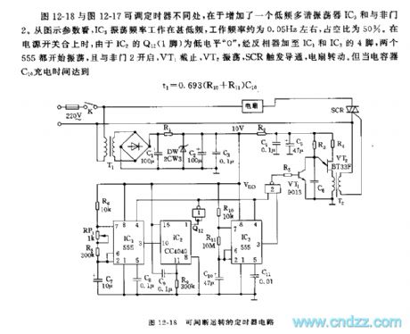
The the difference between adjustable timers in Figure 12-18 and Figure 12-17 is that the earlier is added with a low-frequency multi-resonate oscillator IC3 and a NAND. Judging from the parameters in the figure, the oscillation frequency of IC3 is very low, which is about 0.05Hz, and its duty cycle is 50%. When the power supply switch is closing, as Q12(1-pin) of IC2 is at a low LEV 0 , and the LEV is added to the 4-pin of IC1 and IC3 by the inverter, then both of the 555 start to oscillate, and the NAND 2 opens, VT1 is blocked, VT2 shakes, SCR is triggered and conducting, the fan runs.
(View)
View full Circuit Diagram | Comments | Reading(652)
The 555 natural wind circuit of long timing
Published:2011/5/29 22:33:00 Author:Borg | Keyword: natural wind, long timing
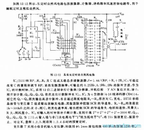
Figure 12-12 the natural wind circuit of long timingIC1(555),RP1,R1,R2 and C consist a non-steady multi-resonate oscillator whose f is 1.44/(RP1+R1+2R2)C, and the frequency can be changed by changing the measuring range of C and adjusting RP1, the frequencies of the output pulse square waves are 0.25Hz,0.5Hz and 1Hz, respectively, which can be the counting clock of IC2. The circuit computes with a 12-degree binary series counter/frequency distributor. When it is on, press the reset switch AN and clean the former numbers, then it starts to count, Q1,Q2,Q3 and Q4 deliver counting pulse to IC3 in turn. IC3 is a 4 bit lock/4-16 wire decoder CD4514. (View)
View full Circuit Diagram | Comments | Reading(501)
Eye-care Lamps (the 5th)
Published:2011/5/20 1:55:00 Author:Felicity | Keyword: Eye-care Lamps (the 5th)
Work of the circuit
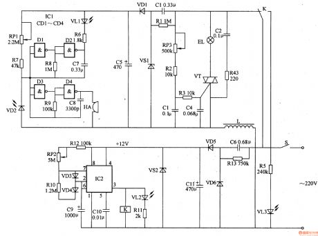
The circuit consists of power circuit, timing control circuit, LED indicating circuit, light changing circuit, light examine circuit and acousto-optic alarm circuit (It is showed in picture 9-72.).
Turn on the switch S and timing control circuit is supplied with +12V working voltage. And the voltage separates into two parts. One lightens the EL in the meantime the other one supplies 9V voltage to light examine circuit and acousto-optic alarm circuit.
Change the value of RP1 to change the sensitivity of light examining circuit. And change the value of RP2 to change the regular timer. (View)
View full Circuit Diagram | Comments | Reading(388)
Car Windshield Wiper Controller (the 2nd)
Published:2011/5/20 2:54:00 Author:Felicity | Keyword: Car Windshield Wiper Controller (the 2nd)
Work of the circuit
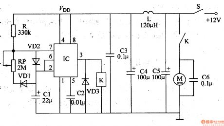
The circuit consists of Multivibrator, control circuit and filtering circuit (It is showed in picture 7-164.).
Turn on the switch S +12v voltage supplies IC with working power. When the Multivibrator is working the pulse signal is outputted from pin 3. When the signal is of high level the motor M starts to work. When the signal is of low level the motor stops working. (View)
View full Circuit Diagram | Comments | Reading(546)
Eye-care Lamps (the 2nd)
Published:2011/5/20 1:51:00 Author:Felicity | Keyword: Eye-care Lamps (the 2nd)
Work of the circuit
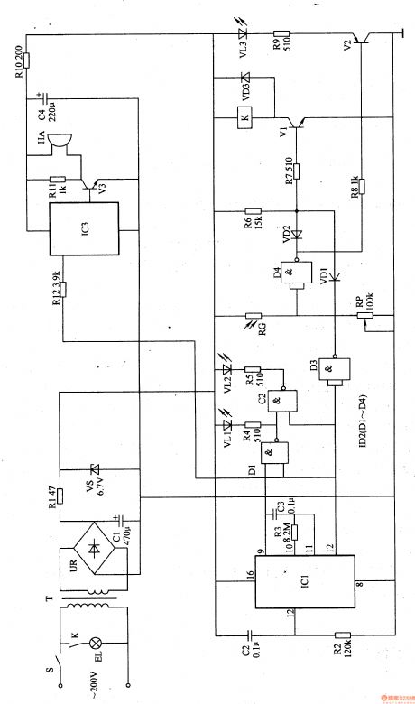
The circuit consists of power circuit, timer, light examine circuit, LED shining circuit, light control circuit and music circuit (It is showed in picture 9-69.).
Turn on the power and the timer begins to work. Lamp EL is lightened but either music circuit or HA works. When the regular time is over EL stops working and HA sends out music to remind the user to have a rest.
Change the value of RP to change the sensitivity of light-dependent control. (View)
View full Circuit Diagram | Comments | Reading(457)
Hearing-aid (the 1st)
Published:2011/5/19 21:17:00 Author:Felicity | Keyword: Hearing-aid (the 1st),
Work of the circuit
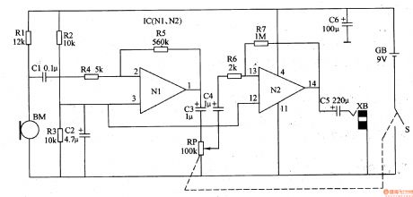
The hearing-aid circuit consists of mike BM, volume potentiometer RP and two-step amplifier circuit (It is showed in picture 9-77.).
Sound signal is collected and translated into electric signal by mike BM. Then it is inputted into IC’s pin 2 through CI and R4 and outputted from pin 1 after being amplified by amplifier N1. At last it is returned to sound by earphone after being amplified by operating amplifier N2.
(View)
View full Circuit Diagram | Comments | Reading(3210)
F2-750A Intelligent fuzzy control rice cooker circuit
Published:2011/5/23 22:48:00 Author:John | Keyword: rice cooker
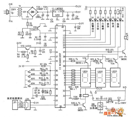
F2-750A Intelligent fuzzy control rice cooker circuit is shown below.
(View)
View full Circuit Diagram | Comments | Reading(937)
MB-YC50A Luxury type rice cooker circuit
Published:2011/5/23 22:31:00 Author:John | Keyword: Luxury type rice cooker

MB-YC50A Luxury type rice cooker circuit includes power supply board circuit ( figue a) and
computer control board circuit (firgue b).
(View)
View full Circuit Diagram | Comments | Reading(639)
555 snore suppressor circuit
Published:2011/5/29 20:41:00 Author:TaoXi | Keyword: 555, snore, suppressor
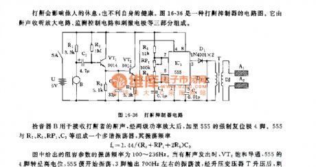
The figure 16-36 shows the snore suppressor circuit, it is composed of the snore receiving circuit, the monitoring control circuit and the stimulating circuit.
The pickup B can be used to receive the snore, the snore is amplified by the two stages power tube, then it adds to the mandatory resetting port pin-4. The multivibrator is composed of the 555 and R5,R6,RP1,C3, the oscillation frequency f=1.44/(R5+RP1+2R6)C3.
The RC parameters' oscillation frequency is 100~236Hz. When there is the snore, VT2 conducts, pin-4 of 555 has the high electric potential, the 555 starts working, pin-3 outputs the 700Hz oscillating wave, and this oscillating wave is boosted by the pressurization transformer T to stimulate both ends of the electrode DJ to produce the 45V electrical pulse.
(View)
View full Circuit Diagram | Comments | Reading(545)
555 simple electrocardiogram validator circuit
Published:2011/5/25 2:18:00 Author:TaoXi | Keyword: 555, simple, electrocardiogram, validator
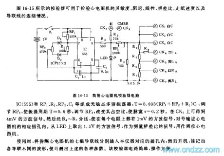
The figure 16-15 shows the validator that can be used to check the sensitivity, the damping, the linearity, the difference distinguishing ratio, the paper passing speed and the guide line connection of the electrocardiogram validator.
The astable multivibrator is composed of the IC(555) ad RP1, R1, RP2, C1, the T=0.693(RP1+RP2+R1)C1. By adjusting RP1, the oscillation period T=0.6 second, and you can change the duty ratio by adjusting RP2, then the pulse width will be 0.2 second. You can get the 4mV square wave signal from CK3. This square wave signal is separated by R4~R7, so each resistance has the square wave signal of 1 mV. You can get out the 1.5V square wave signal from the LED as the difference ratio measurement signal to set the electrocardiogram device.
(View)
View full Circuit Diagram | Comments | Reading(407)
555 simple electric acupuncture anesthesia instrument circuit
Published:2011/5/25 1:48:00 Author:TaoXi | Keyword: 555, simple, electric, acupuncture, anesthesia, instrument

As the figure 16-16 shows, the electric acupuncture anesthesia instrument is composed of the pulse signal source, the trigger circuit and the driving circuit.
The astable multivibrator is composed of the 555 and R1,RP1,C1~C3, the oscillation frequency depends on the charging and discharging time constant of the circuit, f=1.44/(R1+RP1)C. By changing the position of the switch K, you can change of oscillation frequency, also you can adjust the frequency by adjusting the RP1.
IC2 uses the sound control integrated circuit SK-III , it is composed of the amplification shaping circuit, the frequency selection circuit, the trigger circuit and the driving circuit, in this circuit, the SK-III is used as the trigger.
(View)
View full Circuit Diagram | Comments | Reading(3112)
555 electronic eyesight protector circuit
Published:2011/5/23 21:53:00 Author:TaoXi | Keyword: electronic, eyesight protector
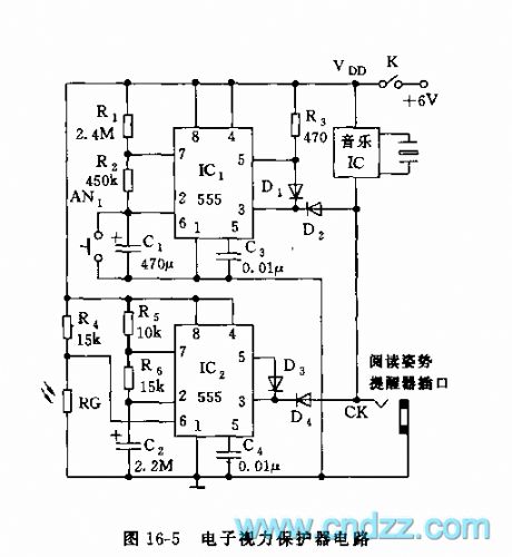
As the figure 16-5 shows, the protector is composed of the reading time limit reminder and the reading environment metering device, and it can be used to protect the students' eyesight.
The multivibrator is composed of the IC1(555) and the R1, R2, C1, the oscillation period T=tcharging+tdischarging, when you are using it, press the AN1, the 555 sets, at the same time, C1 is charged by R1 and R2, the time of charging is about 50 minutes, tcharging=0.693(R1+R2)C1. When pin-6's electrical level is 2/3VDD, the 555 reverses and resets, the pin-3 has the low electrical level, the music IC sends out the voice to remind you to have a rest.
The reading environment metering device is composed of the IC2, R5,R6,C2, R4 and the photoresistor RG, when the reading light intensity is lower than 100 lux, the value of RG becomes higher.
(View)
View full Circuit Diagram | Comments | Reading(465)
555 high voltage generator circuit
Published:2011/5/23 20:43:00 Author:TaoXi | Keyword: high voltage, generator circuit

As the figure 16-18 shows, the high voltage generator uses the 555 as the core, the oscillation voltage is boosted by the step-up transformer. The astable multivibrator is composed of the 555 and R1,R2,C1, the oscillation frequency f=1.44/(R1+2R2)C1, it is about 2000Hz. The 555 oscillation square-wave is amplified by VT1, and is boosted by transformer T1, an then it is rectified by the high-pressure reactor D1, at last we get the 3-5kV DC voltage. The D1 reverse breakdown voltage is higher than 15 kV, VT1's Vced>50V. The transformer T1 outputs the transformer ignition coil by using the 9-12 inches television. The secondary coil is binded by 30 turns of high strength enameled wire with the diameter of 0.6mm.
(View)
View full Circuit Diagram | Comments | Reading(6352)
555 electronic ballast circuit
Published:2011/5/24 2:52:00 Author:TaoXi | Keyword: electronic, ballast
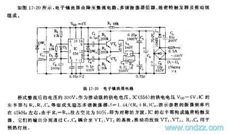
As the figure 17-20 shows, the electronic ballast is composed of the step-down rectifier circuit, the multivibrator source circuit, the Schmitt trigger and the promotion stage.
The bridge rectifying voltage is 300V, and this voltage is used as the promotion stage's power supply voltage. IC(556)'s power supply voltage VDD=6V, the left part of IC and the R6,R1,C9 constitute the astable multivibrator, the oscillation frequency f=1.44/(R6+R1)C9, the parameters of the figure's oscillation frequency is about 45kHz, because R1=R6, so the duty cycle is about 50%, it is the symmetrical square wave. The right part of the IC constitutes the Schmitt trigger.
(View)
View full Circuit Diagram | Comments | Reading(1155)
555 vegetable sterilization and detoxification machine circuit
Published:2011/5/23 19:08:00 Author:TaoXi | Keyword: vegetable, sterilization, detoxification, machine
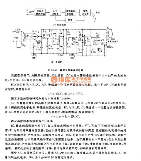
This circuit is composed of the step-down rectifier circuit, the electronic timing circuit, the high frequency oscillation high voltage circuit, the ozone generator and the antioxidant pressure pump.etc, as the figure 16-42 shows.
The AC transformer T1 is the step-down transformer, it's secondary stage has the 10V AC current, and this current is rectified by the full wave to produce the +12V DC current as the power supply of the IC1 and IC2.
The controllable monostable timing circuit is composed of the IC1(555) and R1~R3,C2,AN1.etc. By pressing AN1, you can trigger the monostable state.IC2's high-frequency pulse is amplified by VT1 to drive the high-frequency pulse transformer. The VT1 uses the VMOS type power switch tube.
(View)
View full Circuit Diagram | Comments | Reading(695)
| Pages:175/195 At 20161162163164165166167168169170171172173174175176177178179180Under 20 |
Circuit Categories
power supply circuit
Amplifier Circuit
Basic Circuit
LED and Light Circuit
Sensor Circuit
Signal Processing
Electrical Equipment Circuit
Control Circuit
Remote Control Circuit
A/D-D/A Converter Circuit
Audio Circuit
Measuring and Test Circuit
Communication Circuit
Computer-Related Circuit
555 Circuit
Automotive Circuit
Repairing Circuit