
Signal Processing
Index 167
Dong Fang rice cooker and porridge device circuit
Published:2011/5/27 7:08:00 Author:John | Keyword: rice cooker, porridge device

Rice cooker and porridge device circuit is shown below.
(View)
View full Circuit Diagram | Comments | Reading(668)
RC sine wave oscillator circuit
Published:2011/6/9 21:17:00 Author:John | Keyword: sine wave oscillator


Common RC sine wave oscillator circuit is RC series-parallel sine wave oscillator circuit. It is also called Wien bridge sine wave oscillator circuit.
Series-parallel network here is regarded as an option for frequency and feedback network. The circuit is just shown in Figure (1):
Its starting condition is and its oscillation frequency is .It is mainly used for low-frequency oscillations. To generate a higher frequency sinusoidal signal, the LC sine wave oscillator circuit is generally adopted. Its oscillation frequency is . Quartz oscillator is characterized by its particularly stable oscillation frequency, so it is commonly used in occasions with highly stable oscillation frequency.
(View)
View full Circuit Diagram | Comments | Reading(592)
100-nary counter circuit
Published:2011/6/9 21:19:00 Author:John | Keyword: 100-nary counter

Define the level of integration counter. 1 # chip is low (equivalent to one bit) and 2 # chip is high (the equivalent of ten). Start counting from the low bit and send the counting pulse CP into 1# (low) the CP terminal of integrated counter.
B. Look for carrying signal. It is delivered from the injection terminal C. This is the process for counting from 0 to 9. When Q3Q2Q1Q0 reaches 1001(9), high signal has been delivered. C. 74LS160 is the most effective integration counter for the CP’s rising edge. And the chip at high height requires a high level trigger with rising edge pulse in order to count triggering number. (View)
View full Circuit Diagram | Comments | Reading(438)
Electronic Sterilizer (the 2nd)
Published:2011/5/19 8:23:00 Author:Felicity | Keyword: Electronic Sterilizer (the 2nd),

Work of the circuit
The electronic sterilizer circuit consists of power circuit, control circuit and heating circuit. (It is showed in picture 9-97).Turn on Q’s control derail and press button SI. 220V AC voltage is bucked, rectified, limited and stabilized by CI, VDI, R2, VS. Then the voltage separates into two parts. One lightens VL after being bucked and limited by R4 while the other one supplies the working voltage to K1 and K2 after being bucked and limited by R3 and filtered by C2. (View)
View full Circuit Diagram | Comments | Reading(483)
Disinfectant Manufacturer (the 2nd)
Published:2011/5/19 21:12:00 Author:Felicity | Keyword: Disinfectant Manufacturer (the 2nd),

Work of the circuit
The disinfectant manufacturer circuit consists of power changing circuit, pilot light controlling circuit, electrode driving circuit and timer circuit. (Iit is showed in picture 9-93.).
Put 500ml salting liquor in the cup of Disinfectant Manufacturer and turn on the power. 220V AC voltage produced +6V voltage after being reduced rectified and filtered. The voltage separates into two parts. One of them supplies pole and its driving circuit while the other one supplies to timing circuit, pilot light controlling circuit and pole driving circuit. Here diode VLI starts to work which implies the beginning of work. When the timer has worked for about 60min diode VLI becomes dark which implies that the disinfectant has been done. (View)
View full Circuit Diagram | Comments | Reading(410)
Patient SOS Appliance Two
Published:2011/6/6 9:29:00 Author:Felicity | Keyword: Patient SOS Appliance,

This patient SOS appliance consists of trigger circuit and oscillator. After the patient press S1, +9V voltage put on the gate pole of VT through S2, R3 and S1 to trigger VT on, and the oscillator is on and at work. The oscillator signal at the frequency about 1 KHz is output by pin 3 of IC to drive speaker BL send out a high frequency alarm sound. After the medicine box is open, S1 is off and VT cut off, then oscillator is power off and BL stops. (View)
View full Circuit Diagram | Comments | Reading(488)
1kHz Sinusoidal Oscillator Circuit
Published:2011/5/29 0:59:00 Author:Joyce | Keyword: 1kHz , Sinusoidal Oscillator

As shown in the figure is the 1 kHz sinusoidal oscillator circuit. This circuit would generate 1000Hz sine wave through an ordinary operational amplifier 741 on the basis of double T circuit. To adjust the 100kΩ potentiometer will make the circuit start oscillation, and the oscillation frequency is determined by R1 and R2,which are equal in value generally. The oscillation frequency is inversely proportional to the resistance value. Usually the range of resistance is 4.7 ~ 18 Ω , and when the value of R1 and R2 is set, the required capacitance can be determined. In the above figure, the value of the resistance is 13Ω,and the capacitance is 0.01 / u F and the oscillation frequency is 1kHz. (View)
View full Circuit Diagram | Comments | Reading(2034)
Automatic Timing Controller Circuit Composed of 555
Published:2011/5/29 1:19:00 Author:Joyce | Keyword: Automatic, Timing Controller, 555

As shown in the figure is the automatic timing controller circuit. This circuit constitutes of an electronic watch, detection circuit (C1, D1), amplifying circuit, monostable multiply delay circuits (555, BG3 W2, C6 and), and relay J etc.
And the timing signal source is from the end part of the electronic watch segment C. When the end part P changes into R,the voltage of segment C will rise to 3V.And the signal will be detected D1、C1 and amplified by BG1 and BG2 before it is sent to feet ② of 555 to trigger the operation of 555 circuit. When the negative pulse of BG2 comes, the monostable multiply delay circuit would turn, then feet ③ would output high level, and the time of monostability will be 1.1Rw2C6β,βbeing the amplification factor of the current of BG3. (View)
View full Circuit Diagram | Comments | Reading(451)
Automatic Controller Circuit of Amplification and Exposure Time
Published:2011/5/29 1:35:00 Author:Joyce | Keyword: Automatic Controller, Amplification , Exposure , Time

As shown in the figure is the automatic control circuit of amplification and exposure time . This circuit constitutes of step-down and rectifier circuit, monostable timing circuit and relay control circuit etc.The monostable timing circuit is composed of IC (555)、photosensitive detection head R0,and capacitance C1 ~ C4 etc. The length of timing depends on the time constant of the charging and discharging circuit.R0 is the photoconductive resistance. To stir the switch K2 will have four speed gears of exposure mode, 1, 2, 3 are automatic control, whose possess 3 kinds of exposure:” bright , normal and dark ,while 4 presents manual control. (View)
View full Circuit Diagram | Comments | Reading(425)
Automatic Timing Intermit Irrigation Control Circular Composed of 555
Published:2011/6/2 2:56:00 Author:Joyce | Keyword: Automatic , Timing, Intermit Irrigation , Control , 555

As shown in the figure is an automatic timing intermit irrigation control circuit. This circuit constitutes of a step-down rectifier circuit, an on-off control circuit, harmonic oscillators (R5, R6, 555, W2, C2) and bidirectional triode thyristor SCR control circuit etc.
The humidity sensors need to be connected into the circuit can be two graphite rods with brass caps on both ends. When the soil is dry, the electric conductivity between the two graphite rods is low, so the resistance is large. After differential pressure, BG1 will cut off while BG3 and BG2 will conduct. When the soil is moist, the resistance between the two graphite rods is small, thus BG1will conduct, and BG2, BG3 will cut off .The harmonic oscillators will stop in absence of power supply, and make tube BG4 and SCR cut off. Therefore, the corresponding pumping motor will not work. (View)
View full Circuit Diagram | Comments | Reading(1324)
Class Bell Automatic Controller Circuit Composed of 555
Published:2011/6/2 3:14:00 Author:Joyce | Keyword: Class Bell , Automatic , Controller, 555

As shown in the figure is a class bell automatic controller circuit. It includes a step-down rectifier circuit, a circular program timing circuit, and an executive control circuit etc. IC4~ IC1 are trigger delay circuit, and the delay time can be adjusted by regulating charge-discharge time RC. IC5 is ringing time timing control circuit, and the delay time td5 is 1.1 R13C12. The output of IC4 IC1 in the circular program timing circuit is sent to D1, D2, then goes through capacitor C11 to trigger IC5 to output high level (feet③),which would make the relay actuate, thus supply the bell DLwith power.
(View)
View full Circuit Diagram | Comments | Reading(589)
Fre-tech,fretech
Published:2011/5/23 18:49:00 Author:Michel | Keyword: Fre-tech, fretech
Our company,Shanghai Bozhen Electronics Co.,Ltd is the only agent of Fre-tech's(www.fre-tech.com) military and astronautics class crystal oscillatorsin Chinaand our telephone is 021-59773048.
Welcome to reprint theinformation and itis from www.dzsc.com. (View)
View full Circuit Diagram | Comments | Reading(805)
Principle and Circuit of Transformer Feedback Type Oscillator
Published:2011/6/10 7:27:00 Author:Michel | Keyword: Transformer, Feedback Type, Oscillator, Principle and Circuit
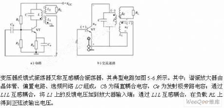
The transformer feedback oscillator is also called mutual-inductance coupling oscillator and it's typical circuit is showed as picture 5-6.The resonant amplifier is composed of transistor,bias circuit and frequency network.Cb is blocking couplingcapacitor,Ce is emittingbypass capacitor .It is coupled via L1L and the L1 feedback voltage is added to amplifier's input end.The sine wave output voltage obtained from load RL by L1L mutual-inductance coupling. (View)
View full Circuit Diagram | Comments | Reading(590)
Oscillator Circuit of Three - Point Capacitance
Published:2011/6/10 7:14:00 Author:Michel | Keyword: Three - Point Capacitance, Oscillator Circuit
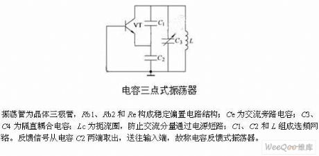
The oscillating tube is rystcal triode and Rb1,Rb2 and Re consititute stable bias circuit.Ce is AC shunt capacitor,itC3 and C4 is blocking coupling capacitor.Lc is choke which prevent the AC componet from passing through the power short-circuit.C1,C2 and L constitute frequency network.The feedback signals output from capcitance C2 and they are transmitted to input end,thus it is called capacitance feedback oscillator. (View)
View full Circuit Diagram | Comments | Reading(880)
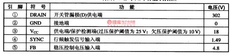
555 FM Circuit
Published:2011/6/9 19:09:00 Author:Michel | Keyword: 555, FM Circuit

Cicuit's FunctionsThe frquency can be modulated once the charging current of 555 free-running multivibrator self- excited multivibrator ip-flop is altered.It's worth noting that it can be used as VCO if the charging current is greatly changed.This kind of oscillator's oscillation frequency is lower than 100 KHZ and the frequency of the circuit is 40 KHZ and it's close to infrared remote control frequency. This circuit also can be modulated as low frequency carrier frequency voice or data signal.
Circuit's Work PrincipleIf modulation frequency range is small, the leads 7 of the oscillating circuit can be connected to the resistance and it masses the blocking condenser stopping capacitor and then the FM moudulation can be constitituted (View)
View full Circuit Diagram | Comments | Reading(9)
Application Circuit of MAX1848
Published:2011/5/25 4:08:00 Author:Joyce | Keyword: Application Circuit of MAX1848

In applications requiring higher power, MAX1848 drive which is based on inductance can be used. MAX1848`s external circuit needs only a few components ,and the conversion efficiency can reach 88% if the output power is 800mW. MAXI848 integrates boost converter and current control circuit in 6 pins 50723 encapsulation.With electric current detection,it drives three groups of white light LED,andeach group includes 3 white light LED connected in parallel as shown in figure. The input voltage range of MAX1848 is 2.6 ~ 5.5 V. MAX1848 uses voltage feedback to adjust the current flowing through the white light LEDs, and smaller current detection resistance (5 Ω) helps to save power and keep high conversion efficiency. In the typical application circuit of MAX1848,the device parameters are: L1 = 33μH, CCOMP = 150nF, COUT = 1.0μF, RSENSE = 5Ω. The current of white light LED is decided by the control voltage: IOUT = UCTRL/( 18.33 xRSENSE).
The luminance of the white light LED can be regulated by DAC of CTRL pins or potentiometer bleeder circuit. And the controllable scope of voltage is + 250mV ~ + 5.5 V. To grounding the control pins shutoff the circuit. (View)
View full Circuit Diagram | Comments | Reading(483)
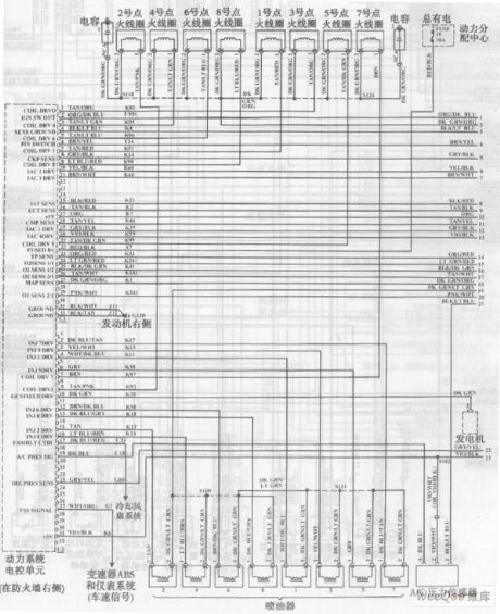
Beijing daqienuoji automobile engine circuit
Published:2011/6/7 3:39:00 Author:Fiona | Keyword: Beijing daqienuoji automobile engine
View full Circuit Diagram | Comments | Reading(523)
FAN8200,FAN820OD--a motor driven integrated circuit
Published:2011/5/18 2:51:00 Author:Borg | Keyword: stepper, motor driven, integrated circuit
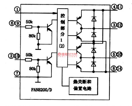

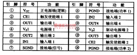
FA820OD and FAN8200D are a kind of integrated circuit of low voltage single door and stepper motors, which can be used in two-phase stepper motor driven systems of digital cameras, disc drivers, safety mobile control and thermal printers.1.function featuresFAN820O and FAN820OD consist of two identical control circuits. The control signals come in from IN point, and into internal controllers after backing-buffered, then they are handled by the control part and drive the NPN, finally, they come out from OUT point as the form of square waves and make the motor run.
2.pin functions
(View)
View full Circuit Diagram | Comments | Reading(458)
555 aphonia throat alternative device circuit
Published:2011/5/25 1:02:00 Author:TaoXi | Keyword: aphonia, throat, alternative device

The IC2(uA741) is designed as the voice amplifier, the amplification number depends on the value of RP2/R3, the maximum is 1000 times. The microphone picks up the throat voice and this throat voice is amplified by the IC2, then adds to VT1. The tone generator is composed of the IC1(555) and RP1, C1, C2, it's output pulse (pin-3) is changed into the triangular wave by C2 and RP1, so it produces the modulation to 555 oscillator to drive the speaker to send out the variable-tones sound waves. This device also can be used in the applications of analog dubbing and the analog tone voice.
(View)
View full Circuit Diagram | Comments | Reading(1170)
555 gradually ringing type sleep wake-up device circuit
Published:2011/5/24 22:56:00 Author:TaoXi | Keyword: gradually, ringing, sleep, wake-up

As the figure 16-3 shows, the delay switch circuit is composed of the IC1 and the R1,C1, the 800Hz multivibrator is composed of the IC2 and R4,R5,C2. When the electric clock's timing contact points turn on the power supply of this circuit,and thecapacitor C1's voltage can not be mutated, so pin-2 of 555 has the high electrical level. At this time, the 555's output port has the low electrical level, the diode D cuts off. When the electric potential of IC1's pin-2 and pin-6 drops to 1/3VDD, the circuit reverses, and the pin-3 has the high electrical level, this charging delay time is about 8 seconds. Then D conducts, the b electrode's potential of the VT1 tube increases.
(View)
View full Circuit Diagram | Comments | Reading(508)
| Pages:167/195 At 20161162163164165166167168169170171172173174175176177178179180Under 20 |
Circuit Categories
power supply circuit
Amplifier Circuit
Basic Circuit
LED and Light Circuit
Sensor Circuit
Signal Processing
Electrical Equipment Circuit
Control Circuit
Remote Control Circuit
A/D-D/A Converter Circuit
Audio Circuit
Measuring and Test Circuit
Communication Circuit
Computer-Related Circuit
555 Circuit
Automotive Circuit
Repairing Circuit