
Signal Processing
Index 178
Eyesight Preserver (the 6th)
Published:2011/5/22 7:06:00 Author:Felicity | Keyword: Eyesight Preserver (the 6th)
Work of the circuit
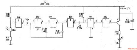
The circuit consists of controlled pulse OSC circuit, trigger controlling circuit, differential circuit, light examining circuit, reshaping circuit and shining driving circuit (It is showed in picture 9-64.).
When the interior light is strong enough the shining diode does not work. When the interior light is rather dim the controlled pulse amplifier starts to work and produces pulse signal. The signal drives shining diode to shine at a regular rate after being adjusted.
(View)
View full Circuit Diagram | Comments | Reading(499)
Eyesight Preserver (the 5th)
Published:2011/5/22 7:05:00 Author:Felicity | Keyword: Eyesight Preserver (the 5th)
Work of the circuit
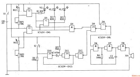
The circuit consists of timing circuit, trigger controlling circuit, light examining circuit, LED indicating circuit and sound warning circuit (It is showed in picture 9-63.).
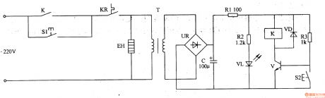
When the environmental light is strong enough the voltage of VD is not so high. Here VL does not shine and HA makes no sound. When the environment light is dim t VL2A shines and HA makes sound to remind the user to flip on the lamp. When the regular time (30min) is reached, HA makes sound to remind the user to have a rest. If the user does not want to stop he can press button S2 to make the timer begin to work again. (View)
View full Circuit Diagram | Comments | Reading(480)
Eyesight Preserver (the 4th)
Published:2011/5/22 7:01:00 Author:Felicity | Keyword: Eyesight Preserver (the 4th)
Work of the circuit
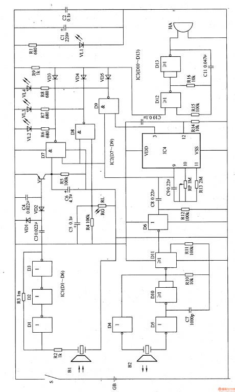
The circuit consists of power circuit, ultrasonic launching circuit, ultrasonic receiving circuit, timing controlling circuit, light examining circuit, LED indicating circuit and sound warning circuit (It is showed in picture 9-62.).
Turn on power switch and the circuit starts to work. When the user’s head is too near from the writing pad (the distance is less than 35cm) VL2 shines and HA makes the sound “tick tick” to alarm the user. When the environmental light is strong enough the voltage of VD is not so high. Here VL does not shine and HA makes no sound. When the environment light is dim the voltage of VD is high. Here VL shines and HA makes sound to remind the user to flip on the lamp. When the regular time is over VL3 is lightened and the HA makes sound to remind the user to have a rest. (View)
View full Circuit Diagram | Comments | Reading(501)
Eyesight Preserver (the 2nd)
Published:2011/5/22 6:57:00 Author:Felicity | Keyword: Eyesight Preserver (the 2nd)
Work of the circuit
The circuit consists of power circuit, ultrasonic launching circuit, ultrasonic receiving circuit, timing controlling circuit, environment light examining circuit and acousto-optic warning circuit (It is showed in picture 9-60.).
Turn on power switch S and battery GB supplies 6V DC voltage to the whole circuit. When the user’s head is too near from the writing pad (the distance is less than 35cm) VL2 shines and HA makes the sound “tick tick” to alarm the user. When the regular time (45min) is over VL3 is lightened and the HA makes sound to remind the user to have a rest. (View)
View full Circuit Diagram | Comments | Reading(473)
Eliminator of Visual Fatigue (the 2nd)
Published:2011/5/22 9:32:00 Author:Felicity | Keyword: Eliminator of Visual Fatigue (the 2nd)
Work of the circuit
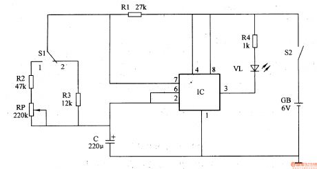
The circuit consists of shining diode V, resistor R1-R4, potentiometer RP, capacitor C, switch S1, S2 and battery GB (I t is showed in picture 9-58.).
When we use the machine we should put it exactly in front of our eyes (the distance should be about 25cm). We look at distance place and when VL shines (2s) our eyes will look at the shining point naturally. When VL stops shining (6s) we should look at the distance place again. In this way can we eliminate fatigue. (View)
View full Circuit Diagram | Comments | Reading(577)
Eliminator of Visual Fatigue (the 1st)
Published:2011/5/22 9:30:00 Author:Felicity | Keyword: Eliminator of Visual Fatigue (the 1st)
Work of the circuit
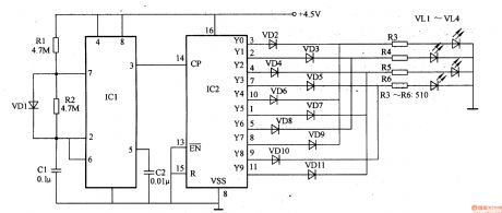
The circuit consists of pulse generator, counting frequency divisor and LED indicating circuit (It is showed in picture 9-57.).
Put four shining diode on the pad symmetrically and the distance between two diodes should be about 30mm. when the eyes are tired they will flex with the shining of the diodes. In this way can the user eliminates the visual fatigue. (View)
View full Circuit Diagram | Comments | Reading(553)
The power failure protection circuit of 555
Published:2011/5/23 5:28:00 Author:Borg | Keyword: power failure, protection circuit
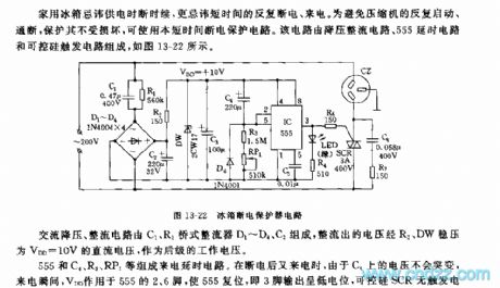
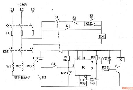
It's a taboo for fridge to get power in intermittence, especially off and on in short times. To avoid the compressor is on and off repeatedly and to protect it from damage, it is proper to use this circuit to protect it temporarily. This circuit consists of step-down rectifier circuits, 555 relaying circuit and controllable trigger circuits, see as Figure 13-22.
AC step-down rectifier circuit consists of C1,R1,bridge rectifier D1~D4 and C2, the rectified current becomes a CD voltage of VDD=10V after being stabilized by R2 and DW, then it becomes a continuing working voltage. (View)
View full Circuit Diagram | Comments | Reading(622)
555 acupuncture point detector circuit
Published:2011/5/23 7:48:00 Author:TaoXi | Keyword: acupuncture point, detector
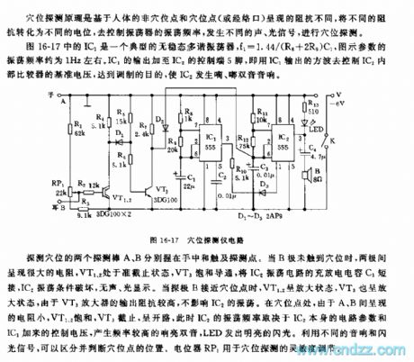
As the figure 16-17 shows, IC1 is a typical astable multivibrator, f1=1.44/(R8+2R9)C1, the parameters' oscillation frequency in the figure is about 1Hz. IC1's output adds to the pin-5of IC2's control port, that uses IC1's output square wave to control IC2 internal comparator's reference voltage, so we achieve the purpose of modulation, IC2 sends out the diplophonia of di du .
At the acupuncture point, the resistance between A and B is small, so VT1 and VT2 is saturated, VT3 cuts off, at this time IC2's oscillation frequency depends on the circuit parameters of IC2 itself and the control voltage of IC1, this circuit produces the higher frequency loud diplophonia, and the LED issues the flashlight.
(View)
View full Circuit Diagram | Comments | Reading(2152)
555 sleep induction unit circuit
Published:2011/5/23 18:54:00 Author:TaoXi | Keyword: sleep, induction unit
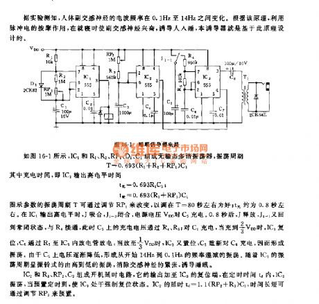
As the figure 16-1 shows, the astable multivibrator is composed of the IC1 and R1,R2,RP1,D1,C1, the oscillation period T=0.693(R1+R2+RP1)C1.
The figure parameters' oscillation period T can be changed by adjusting RP1, it is about 80 seconds as well; tcharging is about 0.8 second. When IC1 outputs the high electrical level, J and J1-1 close, the power voltage VDD charges the C5. After 0.8 second, J releases, J1-1 returns to the closing state, the R4 is connected, so the C5's charging voltage gets through the R4 and R5.
(View)
View full Circuit Diagram | Comments | Reading(935)
555 intermittent type ozone generator circuit
Published:2011/5/23 19:18:00 Author:TaoXi | Keyword: intermittent type, ozone generator
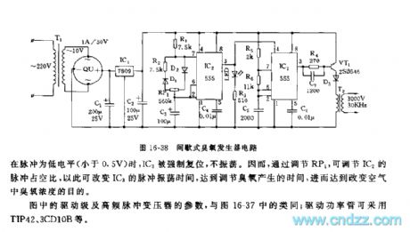
The ozone generator circuit is as shown in the figure 16-38, it is composed of the low-voltage power supply circuit, the ultralow frequency pulse oscilation circuit, the high-frequency multivibrator and the high-frequency pulse excitation stage.etc.
The low-frequency multivibrator is composed of the IC2(555) and R1,R2,D1,D2,RP1,C3, the oscillation frequency f=1.44/(R1+R2+RP1)C3.
The figure parameter's oscillation frequency is about 0.025HZ, the oscillation period is 40 seconds. By adjusting RP1, you can change the duty ratio of the oscillation pulse. The controllable multivibrator is composed of the IC3(555) and R5,R6,C5, the oscillation frequency f=1.44/(R5+2R6)C5.
(View)
View full Circuit Diagram | Comments | Reading(4012)
Disinfectant Manufacturer (the 3rd)
Published:2011/5/19 21:11:00 Author:Felicity | Keyword: Disinfectant Manufacturer (the 3rd),
Work of the circuit
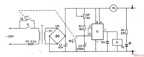
The disinfectant manufacturer circuit consists of power circuit, control circuit. (It is showed in picture 9-94.)
When you press button s 220V AC voltage will produce 5V DC voltage after being reduced, rectified and filtered by T, UR and CI. The voltage will separate into three parts. One is supplied to pole a, b and one lightens VL while another works as power of timing control circuit. If you increase the distance between pole a and pole b, the working current will decrease. (View)
View full Circuit Diagram | Comments | Reading(504)
Thermostat for Medical (the 3rd)
Published:2011/5/22 9:36:00 Author:Felicity | Keyword: Thermostat for Medical (the 3rd)

Work of the circuit
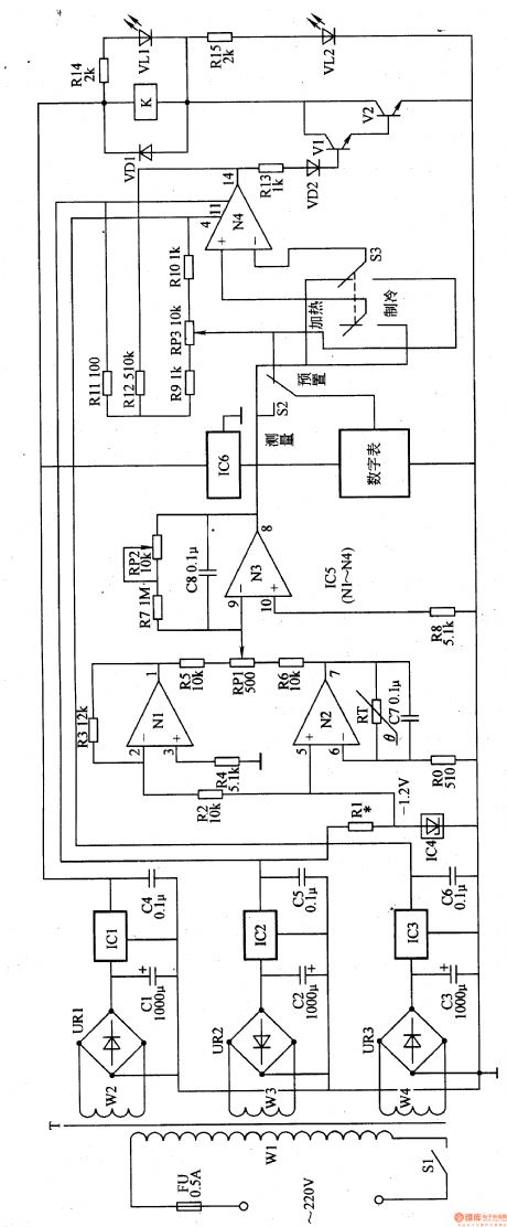
The circuit consists of power circuit, infrared controlling circuit, temperature examining circuit and temperature unusual warning circuit (It is showed in picture 9-42.).
When the temperature is lower than the reset temperature the semiconductor refrigerator starts to work and heat. And when the reset temperature is reached it stops working. In this way the temperature of the thermostat is kept in a reset range.
When the temperature is higher than the reset temperature the semiconductor refrigerator starts to work and refrigerate. And when the reset temperature is reached it stops working. In this way the temperature of the thermostat is kept in a reset range. (View)
View full Circuit Diagram | Comments | Reading(2012)
Thermostat for Medical (the 2nd)
Published:2011/5/22 9:35:00 Author:Felicity | Keyword: Thermostat for Medical (the 2nd)
Work of the circuit
The circuit consists of power circuit, temperature examining circuit and controlling executing circuit (It is showed in picture 9-41.).
When we use it to heat we should put S2 in the site “heating”. If the temperature is higher than the reset temperature the heating circuit does not work. If the temperature is lower than the reset one the heating circuit works.
When we use it to refrigerate we should put it in the site “refrigeration”. If the temperature is higher than the reset temperature the refrigerating circuit works. If the temperature is lower than the reset one the refrigerating circuit does not work.
(View)
View full Circuit Diagram | Comments | Reading(484)
Pulse delay generating circuit composed of the SN7490
Published:2011/5/19 20:19:00 Author:Christina | Keyword: Pulse delay generating
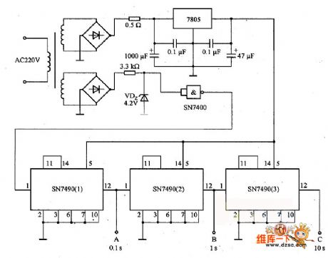
The pulse delay generating circuit composed of the SN7490 is as shown. It uses the 220V、50Hz AC as the standard delay pulse generating circuit. In the circuit, port A can output 0.1s delay pulse, port B can output 1s delay pulse, port C can output 10s delay pulse. This circuit is the standard pulse circuit and also the basic form circuit of the digital counter.
(View)
View full Circuit Diagram | Comments | Reading(1133)
Electronic Sterilizer (the 1st)
Published:2011/5/19 8:20:00 Author:Felicity | Keyword: Electronic Sterilizer (the 1st),
Work of the circuit
The electronic sterilizer circuit consists of power circuit, control circuit. (It is showed in picture 9-96.)Process circuit and press SI. 220V AC voltage supplies 12V direct-current working voltage after being reduced, rectified, filtered, bucked and limited by T, UR, C and RI. The voltage makes V conducted and lightens VL in the meantime. If you want to stop heating in the process of heating and sterilizing you can press S2 and cut off the machine’s power. (View)
View full Circuit Diagram | Comments | Reading(603)
The light and signal circuit of DPCA-VOLCANE DC7140 ZX
Published:2011/5/19 19:48:00 Author:Borg | Keyword: light and signal circuit, DPCA-VOLCANE
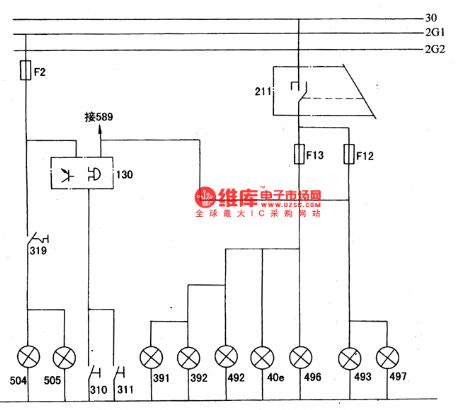
The transmission between high and low beams is fulfilled by pulling the handling behind.
The lighting and signal circuit of DPCA-VOLCANE DC7140 ZX40e-position indicator; 130-alarm for not-off light; 211-left combination switch; 310,311-left-right front door lamp switch; 319-brake lamp switch; 391.392-left and right license lamp; 492,493-left-front and right-front position lamp; 496,497-left-rear and right-rear position lamp; 504,505-left and right brake lamp; 589-danger alarm lamp switch. (View)
View full Circuit Diagram | Comments | Reading(555)
INA217 Signal And Power Supply Basic Connection Circuit
Published:2011/5/17 21:42:00 Author:Robert | Keyword: Signal, Power Supply, Basic Connection

The INA217 Signal And Power Supply Basic Connection Circuit is shown below.
(View)
View full Circuit Diagram | Comments | Reading(728)
TA8256HV31.5 supper bass processing integrated circuit
Published:2011/5/11 5:23:00 Author:chopper | Keyword: supper bass processing, integrated circuit
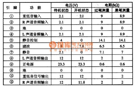
TA8256HV31.5 is a new audio signal amplification integrated circuit manufactured by Toshiba.It is applied to audio device and new large-screen color TV.1.Functional characteristicsIn the TA8256HV31.5 integrated circuit there are three audio processing circuits with the same function and audio signal.Two of them process the sound channel signal of R,L;the other one processes supper bass signal.2.Function and data of pinsTA8256HV31.5 integrated circuit is applied to Changhong CN-l5 chipset color TVs,its function and data of pins of the integrated circuit is shown as following table 1.
(View)
View full Circuit Diagram | Comments | Reading(478)
Ward Caller Four
Published:2011/5/18 8:46:00 Author:Felicity | Keyword: Ward Caller,
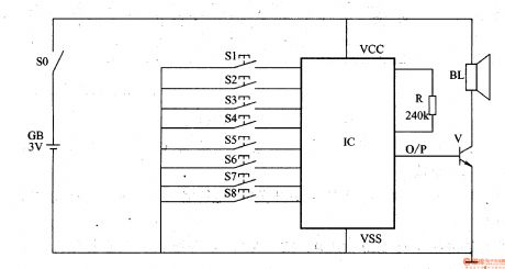
Turn the power switch on, and the circuit is electrified. While S1-S8 is not pressed, O/P port of IC has no output, and BL is noiseless. Once one of the S1-S8 buttons is pressed, IC will be triggered on. And O/P port outputs an electrical signal of the sound effect( Press S1-S8 in order, and O/P port of IC outputs “ Bed number one calling, Bed number two calling...Bed number 8 calling ), and then the electrical signal is amplified by V to drive BL sends out a simulative voice. And the medical personnel can know the number of calling bed according to the vocal calling number. (View)
View full Circuit Diagram | Comments | Reading(530)
Optical Fiber Data Transmission Coupling Circuit
Published:2011/5/17 1:21:00 Author:Sharon | Keyword: Optical Fiber, Data Transmission, Coupling
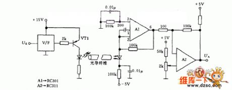
The first step is to transform input analog signal to frequency signal through input voltage frequency converter V/F and then send it to optical fiber by light-emitting diodes. The length of optical fiber or polystyrene rod depends on the separative voltage between digital or analog signals and the photodiode. Photodiode can drive a 100mA output operational amplifier A1, and can further drive cables, relays, or loudspeaker after being amplified byop-amp A2. LEDs can apply MV50 with output amount to 200mA. A1 can apply RC301 operational amplifier, and A2 RC311 can use operational amplifier.
(View)
View full Circuit Diagram | Comments | Reading(1041)
| Pages:178/195 At 20161162163164165166167168169170171172173174175176177178179180Under 20 |
Circuit Categories
power supply circuit
Amplifier Circuit
Basic Circuit
LED and Light Circuit
Sensor Circuit
Signal Processing
Electrical Equipment Circuit
Control Circuit
Remote Control Circuit
A/D-D/A Converter Circuit
Audio Circuit
Measuring and Test Circuit
Communication Circuit
Computer-Related Circuit
555 Circuit
Automotive Circuit
Repairing Circuit