
Signal Processing
Index 163
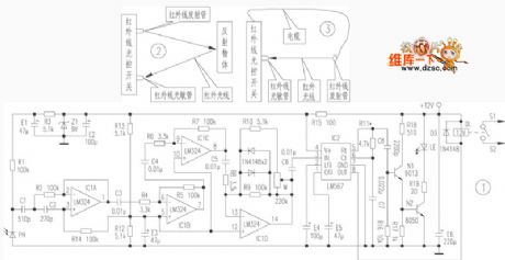
The infrared circuit principle diagram
Published:2011/6/23 2:43:00 Author:qqtang | Keyword: infrared circuit, principle diagram
View full Circuit Diagram | Comments | Reading(439)
Pulse generator circuit uses the interrupt beam
Published:2011/6/22 3:47:00 Author:TaoXi | Keyword: Pulse generator, interrupt beam
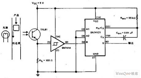
When the object on the band carrier keeps out the light, this circuit will output a pulse. The light source makes the photoelectric transistor to keep in the conduction state. This will produce a high logic level voltage on the Schmitt inverter, and it also produces the low logic level voltage on the pin-5 of the monostable circuit which is compatible with the TTL. When the object keeps out the light, the TIL81 turns off the Schmitt inverter to trigger the monostable circuit.
(View)
View full Circuit Diagram | Comments | Reading(592)
Temperature compensation circuit composed of the piezoresistive pressure sensor
Published:2011/6/22 21:13:00 Author:TaoXi | Keyword: Temperature, compensation circuit, piezoresistive, pressure sensor
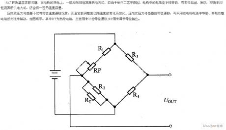
In order to solve the problem of temperature drift, you usually use the constant current source power supply mode. But because the reasons of production process.etc, the resistances of the bridge are not the same, they have the zero position output. So even we use the constant current source power supply mode, there will still be a certain temperature error.
The piezoresistive pressure sensor has the temperature drift phenomena, and the sensitivity changes with the temperature. You can use add the thermistor in the bridge circuit to solve the zero drift of the pressure sensor. As the figure shows, the RT is the thermistor which is mainly used to compensate for the zero drift; the RP can be used to adjust the zero position output.
(View)
View full Circuit Diagram | Comments | Reading(1703)
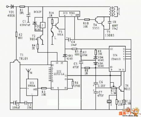
The key ring wireless encoding remote control circuit (2)
Published:2011/6/23 2:04:00 Author:qqtang | Keyword: key ring, wireless encoding, remote control

View full Circuit Diagram | Comments | Reading(670)
The remote control emitting component CS900 circuit
Published:2011/6/22 3:11:00 Author:Borg | Keyword: remote control, emitteing component
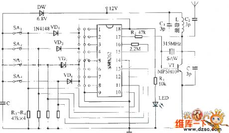
Figure: The remote control emitting component CS900 circuit (View)
View full Circuit Diagram | Comments | Reading(493)
The precise triangular wave oscillator circuit
Published:2011/6/22 2:50:00 Author:Borg | Keyword: precise, triangular wave, oscillator
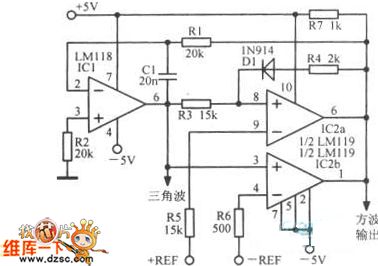
The precise triangular wave oscillator circuit is shown as above.
(View)
View full Circuit Diagram | Comments | Reading(531)
The principle diagram of photocoupler application circuit
Published:2011/6/20 0:55:00 Author:Seven | Keyword: principle diagram, application circuit
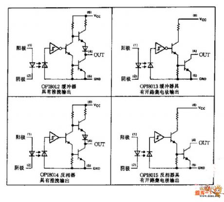
The principle diagram of photocoupler application circuit is shown in the figure.
(View)
View full Circuit Diagram | Comments | Reading(722)
The analytical circuit of the multi-function remote alarm controller
Published:2011/6/21 22:41:00 Author:qqtang | Keyword: analytical circuit, multi-function, remote
View full Circuit Diagram | Comments | Reading(428)
The key ring wireless encoding remote control circuit (1)
Published:2011/6/21 22:32:00 Author:qqtang | Keyword: key ring, remote control
View full Circuit Diagram | Comments | Reading(549)
50Hz rectangular wave generator circuit
Published:2011/6/13 6:59:00 Author:Christina | Keyword: 50Hz, rectangular wave, generator
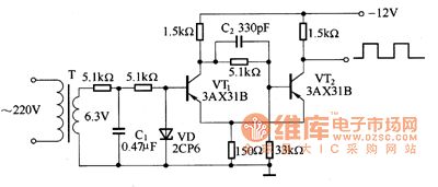
The figure shows the Schmidt shaping circuit that changes the sinusoidal voltage into the rectangular wave. The sinusoidal voltage which is reduced by the transformer adds to the base electrode of VT1 directly. In the positive half cycle of the alternating current, the diode VD conducts, the base electrode electric potential of VT1 is positive, so the VT1 cuts off, VT2 conducts. In the negative half cycle of the alternating current, the base electrode electric potential of VT1 is negative, VT1 conducts and the 5OHz rectangular wave is output by the collector electrode of VT2.
Figure The 50Hz rectangular wave generator circuit
(View)
View full Circuit Diagram | Comments | Reading(483)
The simple ore radio circuit
Published:2011/6/21 6:25:00 Author:qqtang | Keyword: ore radio

View full Circuit Diagram | Comments | Reading(2491)
The key ring type wireless encoding remote control circuit (2)
Published:2011/6/19 21:18:00 Author:qqtang | Keyword: key ring type, remote control

View full Circuit Diagram | Comments | Reading(442)
The full-wave control circuit of the serially connected motor
Published:2011/6/19 21:07:00 Author:qqtang | Keyword: full-wave control, serially connected motor

View full Circuit Diagram | Comments | Reading(434)
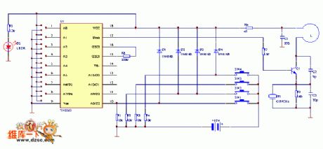
The nerve muscle therapeutic apparatus circuit
Published:2011/6/19 21:05:00 Author:qqtang | Keyword: therapeutic apparatus

The nerve muscle therapeutic apparatus circuit is suitable for middle/old people, office people,high physical labourers and athletes, which has certain function on acute/chronic around nerve illness, muscle injury and muscle strain, etc.Working principle: the circuit is shown in the figure. CD4060 is a time sequence frequency distributor with a oscillator. The frequency of the oscillator is decided by C1,R10,R11 and W1, by adjusting W1, the oscillating frequency can be changes, so that the rhythm of the massage can be changed. After the oscillating signal is split from the inside.
(View)
View full Circuit Diagram | Comments | Reading(539)
The 1~20MHz clock mixer circuit
Published:2011/6/19 21:31:00 Author:qqtang | Keyword: clock mixer
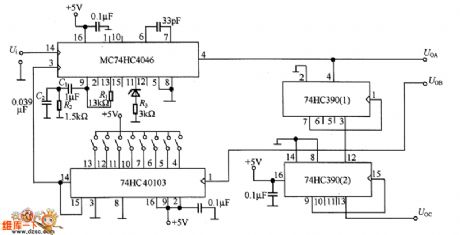
In the figure is the 1~20MHz clock mixer circuit which can generate precise clock signals. UoA outputs the 1~20MHz signal whose resolution ratio is 100KHz, but UoB and UoC output signals whose frequency is 1/10 of the former. If the input signal Ui is 10KHz, which is got by splitting the crystal circuit, then the precision is the same as the crystal oscillator.
(View)
View full Circuit Diagram | Comments | Reading(468)
The MB1570 circuit
Published:2011/6/19 21:38:00 Author:qqtang | Keyword: circuit
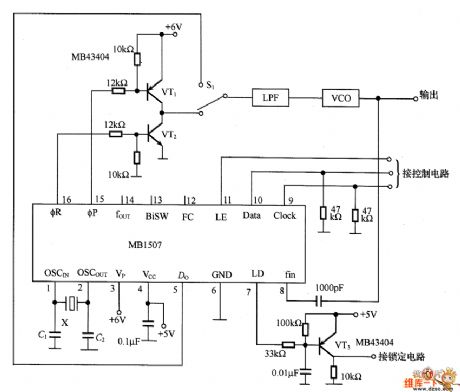
In the figure is the example of the MB1570 circuit, which is a Pl-I mixer integrated circuit, and the band width is 26Hz.
(View)
View full Circuit Diagram | Comments | Reading(437)
The DC sector reverser power circuit of active clamping resonance
Published:2011/6/19 8:20:00 Author:Seven | Keyword: DC sector, active clamping resonance
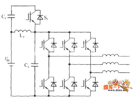
The DC sector reverser power circuit of active clamping resonance is shown in the figure.
(View)
View full Circuit Diagram | Comments | Reading(444)
The digital frequency doubler of square wave output formed by MIC74121
Published:2011/6/17 9:28:00 Author:Borg | Keyword: digital frequency doubler, square wave
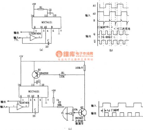
In the figure is the digital frequency doubler of square wave output. Usually, a digital frequency doubler works by the 2 output narrow pulses which are generated by the front-end and rear-end of the input pulse. In figure (a) is a basic frequency doubler circuit, A1, A2 and B are the triggering front-end of the single stable multi-resonance oscillator (MIC74121). Only when either of A1 and A2 is 1 , the other is 0 and B is 1 is the circuit triggered. After the rising edge of the input signal goes along td (the transiting time delay of the phase inverter), the single steady multi-resonance oscillator is triggered. (View)
View full Circuit Diagram | Comments | Reading(2548)
The rectangle pulse frequency doubler
Published:2011/6/17 9:01:00 Author:Borg | Keyword: rectangle pulse, frequency doubler
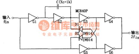
In the figure is the rectangle pulse frequency doubler circuit. This circuit is a digital frequency doubler, which consists of a 6-inverting-phaser MC840P, 2 diodes and a capacitor, and its working frequency is 1Hz~100KHz. The input signal of the circuit is a square wave, and the output is an approximately symmetric rectangle wave. The required capacitive reactance of capacitor C at the frequency is 1kΩ. If the required output is a symmetric square wave, we can connect the capacitor with a resistor in serial or parallel way. The output circuit includes the phase inverters of G3, G4, G5 and G6, and they are coupled by the diodes of D1 and D2. (View)
View full Circuit Diagram | Comments | Reading(823)
The 150-300MHz frequency multiplier composed of MC1596
Published:2011/6/17 20:13:00 Author:Borg | Keyword: frequency multiplier
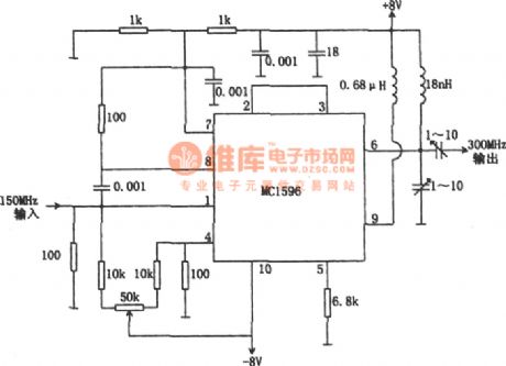
In the figure is the 150-300MHz frequency multiplier. The circuit is made of MC1596 balance modem, whose input frequency is 150MHz and the output frequency is 300MHz. MC1596 has two frequency input terminals(1-pin and 4-pin), and the 150MHZ frequency is added on the two terminals. By adjusting the 50kΩ potentiometer, the two terminals receive the same signal. By adjusting the 2 1~10pF adjustable capacitor, the output frequency will be precisely be twice of the input frequency and the distortion is reduced to the minimum. The input and output impedance are approximate 50Ω. (View)
View full Circuit Diagram | Comments | Reading(1855)
| Pages:163/195 At 20161162163164165166167168169170171172173174175176177178179180Under 20 |
Circuit Categories
power supply circuit
Amplifier Circuit
Basic Circuit
LED and Light Circuit
Sensor Circuit
Signal Processing
Electrical Equipment Circuit
Control Circuit
Remote Control Circuit
A/D-D/A Converter Circuit
Audio Circuit
Measuring and Test Circuit
Communication Circuit
Computer-Related Circuit
555 Circuit
Automotive Circuit
Repairing Circuit