
Signal Processing
Index 176
The low-voltage starting controller circuit of 555 ceiling fans
Published:2011/5/29 19:44:00 Author:Borg | Keyword: low-voltage, starting controller
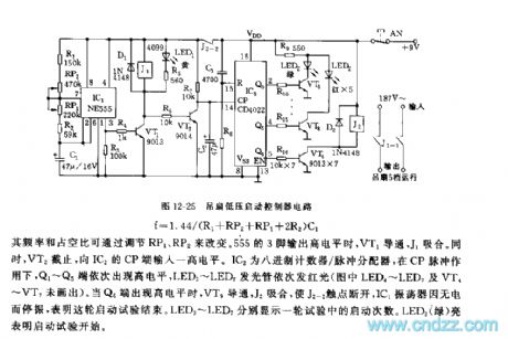
See as Figure 12-25, the low-voltage starting controller is based on two integrated circuits, which is used to do auto-control in the low-voltage starting trial of ceiling fan. 555,R1,RP1,RP2,R2 and C1 consist a non-steady multi-resonate oscillator, and the oscillating frequency is : F=1.44/(R1+RP2+RP1+2R2)C1
Figure 12-25 The low-voltage starting controller circuit of ceiling fans
The frequency and duty cycle can be changed by RP1 and RP2. When the 3-pin of 555 outputs a high LEV, VT1 is conducting and J1 is pulling in. In the meantime, VT2 is blocked and delivers a high LEV to the CP terminal of IC2. IC2 is an octal counter/pulse distributor. (View)
View full Circuit Diagram | Comments | Reading(442)
The 555 multi-functional fan controller circuit
Published:2011/5/28 21:44:00 Author:Borg | Keyword: multi-functional fan
See as figure 12-15, the controller includes the step-down rectifier circuit, time-based pulse generator, frequency distributor, high-speed starting timing circuit, wind switching circuit and controllable trigger circuit. The most noticeable character of this controller is that its rotating speed changes with the working time. When it is starting, the fan runs at a high speed, and it switches into the analog natural wind mode automatically in dozens of seconds. And the circuit can also used as a timed stepless governor. Besides, the circuit can also be used as the light adjuster, temperature controller, timer and so on of lamps and electric appliances, after it is adjusted.
(View)
View full Circuit Diagram | Comments | Reading(383)
The integrated controller circuit of 555
Published:2011/5/28 21:59:00 Author:Borg | Keyword: integrated controller
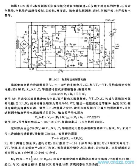
See as Figure 12-22, the controller can fulfill stepless timing and stepless speed adjusting, which can not only control fans, but also control heaters and motors, and its timing span is long and precision is high. This circuit includes the speed adjuster, timer, interval switch, chief switch and power supply,etc.
Figure 12-22 The integrated controller circuit The step down circuit provides a DC voltage of +12v for the controller. IC1, VT1~VT2 and so on consist the speed adjuster control circuit, while 555,R3,R4 and C3 consist the controllable multi-resonate oscillator, the oscillating period is T=0.693(R3+R4+RP1)C3. (View)
View full Circuit Diagram | Comments | Reading(440)
The auto controller circuit of 555 fans
Published:2011/5/28 22:12:00 Author:Borg | Keyword: auto controller
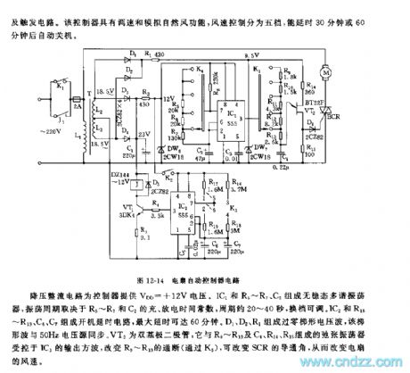
See as Figure 12-14, the controller includes the step-down rectifier circuit, low-frequency oscillator, timing circuit, controllable silicon conduction angle controller and trigger circuit. This controller has functions of speed adjusting and simulating natural wind, the wind speed is classified into 5 levels, and it can delay for 30min or 60min before the fan is power-off.
The step-down circuit offer the controller a voltage of +12V. IC1,R5~R7 and C2 consist a non-steady multi-resonate oscillator, whose oscillating period depends on the charging and discharging time parameters of R5~R7 and C2, the period ranges 20 to 40s which can be adjusted by shifting gears. (View)
View full Circuit Diagram | Comments | Reading(439)
The programme controller circuit of 555 fans
Published:2011/5/29 6:30:00 Author:Borg | Keyword: programme controller
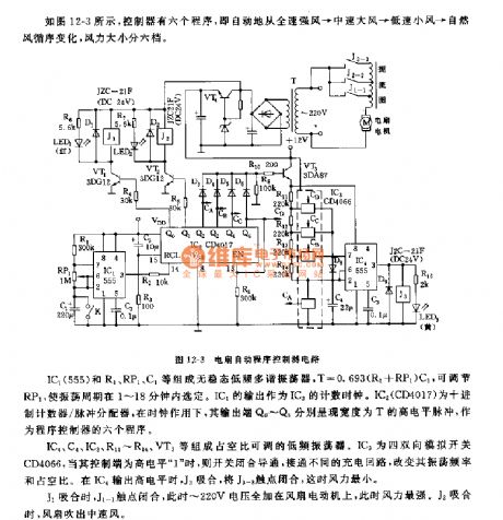
IC4,C4,IC3,R11~R14,VT3 and so on consist a low-frequency oscillator whose duty cycle can be adjustable. IC3 is a 4-two-way analog switch CD4066, when the control pole is in a high LEV 1 , the switch closes and becomes conducting, the frequency and duty cycle can be changed by connecting with different charging circuits. When IC4 outputs a high LEV, J3 pulls in and the contact of J3-3 is closed, at the moment, the wind is the weakest. When J1 pulls in, J1-1 is closing, and now all the voltage of 220V is imposed on the fan motor, so the wind is the strongest. When J2 pulls in, the fan generates intermediate speed winds. (View)
View full Circuit Diagram | Comments | Reading(461)
The temperature controller circuit of 555 fans
Published:2011/5/29 6:47:00 Author:Borg | Keyword: temperature controller
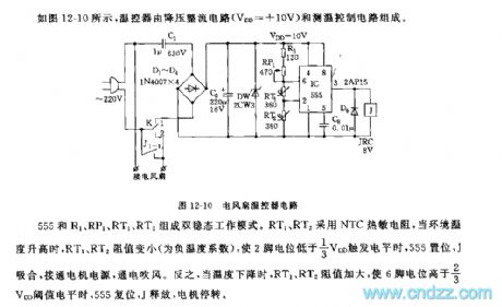
See as Figure 12-10, the temperature controller consists of the step-down rectifier circuit (VDD=+10V) and temperature detection control circuit.
555,R1,RP1,RT1 and RT2 form a dual steady working mode. RT1 and RT2 is made of NTC thermistors, when it gets hotter outside, the resistances of RT1 and RT2 turn lower(the temperature coefficient is negative), which makes the LEV on 2-pin is low than the trigger LEV of 1/3VDD and 555 is offset, J pulls in, the motor power supply is connected. Otherwise, when it's cooler outside, the resistances of RT1 and RT2 are rising,which makes the LEV of 6-pin higher than the threshold value LEV of 2/3VDD, 555 is reset and J is released, so the motor stops. (View)
View full Circuit Diagram | Comments | Reading(1380)
The interval power supply outlet circuit of 555 fans
Published:2011/5/29 7:07:00 Author:Borg | Keyword: power supply outlet
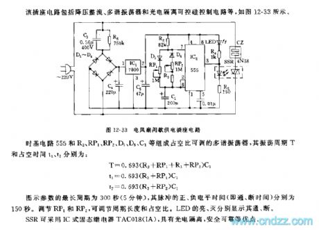
The time-based circuit 555, R2,RP1,RP2,D5,D6,C1 and so on consist a multi-resonate oscillator whose duty cycle is adjustable, the shaking period T and duty cycle times t1 and t2 are: T=0.693(R2+RP1+R3+RP2)C1 t1=0.693(R2+RP1)C1 T2=0.693(R3+RP2)C1The longest period of the figured parameter is 300s(5min), and the positive and the negative times (i.e on/off time) of the pulse are 150s,respectively. The period span and duty cycle can be adjusted by RP1 and RP2. The lighting or not of LED means on or off, respectively. SSR is fixed with IC solid relay TAC018(IA), which has advantages of photo-electricity separation and safety. (View)
View full Circuit Diagram | Comments | Reading(458)
The protector circuit of 555 air-conditioning
Published:2011/5/29 21:28:00 Author:Borg | Keyword: protector circuit, air-conditioning
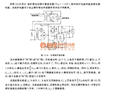
When the air-conditioner is at the wind gear(or cold gear) and it is on, as the voltage on C2 can not mutate, so 555 is offset, J2 keeps still, J2-2 is off, the compressor gets no power and can't start. When C2 engages in charging by R1, after the delaying time td=1.1R1C2, which is about 3min, the LEV of 6-pin rises to 2/3VDD, and that makes 555 reset, J2 pull in and the compressor gets power. At the moment, J1 pulls in and gets power, J1-1 and J1-4 close, J1-1 and J1-3 cut off, and the 555 is in a compelled reset state, the 3-pin is in a low LEV which makes J2-2 to be connected. (View)
View full Circuit Diagram | Comments | Reading(445)
Midea CFXB40-32 Rice Cooker circuit
Published:2011/5/23 20:53:00 Author:John | Keyword: Rice Cooker
Midea CFXB40-32 Rice Cooker circuit is shown below.
(View)
View full Circuit Diagram | Comments | Reading(1261)
HeyGey GDS65-C computer type multi-use rice cooker circuit
Published:2011/5/23 20:59:00 Author:John | Keyword: multi-use rice cooker

HeyGey GDS65-C computer type multi-use rice cooker circuit is shown below.
(View)
View full Circuit Diagram | Comments | Reading(666)
Aihua CFXB double light insulation automatic rice cooker circuit
Published:2011/5/24 0:15:00 Author:John | Keyword: automatic rice cooker

Aihua CFXB double light insulation automatic rice cooker circuit is shown below.
(View)
View full Circuit Diagram | Comments | Reading(1487)
Microwave circuit
Published:2011/5/23 23:28:00 Author:John | Keyword: Microwave
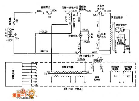
Microwave circuit is shown below.
(View)
View full Circuit Diagram | Comments | Reading(1273)
555 acute coronary artery blood-supply insufficiency alarm circuit
Published:2011/5/24 2:54:00 Author:TaoXi | Keyword: acute coronary artery, blood-supply, insufficiency, alarm circuit
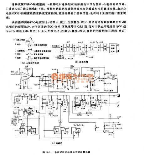
The acute or chronic myocardial infarction disease's omen is the acute coronary artery blood-supply insufficiency, and the heart waves obvious variation. The principle of the alarm circuit: changes the amplitude variation into the width variation.
In the circuit, the IC1 is the monostable trigger, the timing time t2=1 minute; IC2 is the monostable trigger, the timing time t3=2 minutes; it controls the on-off of the IC9 and IC10 alarm circuit's power supply voltage. IC9 is the low frequency astable multivibrator, it produces the 1Hz square-wave signal to control the multivibrator (the oscillation frequency is 1000Hz) IC10's control port pin-5 to produce the variable tones audio alarm signal.
(View)
View full Circuit Diagram | Comments | Reading(892)
555 breath monitor circuit
Published:2011/5/23 20:04:00 Author:TaoXi | Keyword: breath, monitor

As the figure 16-12 shows, the monostable trigger is composed of the 555 time base circuit, and this circuit connects with a external transistor, the lost pulse detection circuit is composed of the external transistor and the monostable trigger. S1 is the air switch. When this circuit is used in the patient's breath monitor application, if the interval of the two respiratories overs the pre-set time, this circuit sends out the alarm signal to remind the health care workers or guards. When the breath is normal, the air switch S1 opens and closes with the breath, R2 is set in the longest time of the twice reset pulse, if it is not resetting in a given period of time, 555 will output the low electrical level.
(View)
View full Circuit Diagram | Comments | Reading(1028)
555 electronic timing, hypnosis and massager circuit
Published:2011/5/23 21:12:00 Author:TaoXi | Keyword: electronic, timing, hypnosis, massager
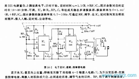
As the figure 16-2 shows, the monostable timing circuit is composed of the IC1 and R1,RP1,C1, An is the timing start-up button, if you press AN, the 555 circuit sets, pin-3 has the high electrical level, and the timing begins. The timing time td=1.1(R1+RP1)C1, the corresponding timing time of the figure parameters is between 10 to 60 minutes, and it is adjustable. The astable multivibrator is composed of the IC2 and R3,RP2,C3, the oscillation frequency f=1.44/(R3+RP2)C3, the figure parameters' oscillation frequency is 0.7-10Hz, you can adjust it by RP2, during the IC1's timing time, this circuit sends out the voice of raindrop to encourage people to sleep, when the timing time is up, it automatically stops the sound.
(View)
View full Circuit Diagram | Comments | Reading(553)
The 555 electronic fishing game circuit
Published:2011/5/25 3:26:00 Author:nelly | Keyword: electron, fishing game, circuit

As shown on the figure 11-6, the fishing circuit consists of timing circuit and audio circuit. 555, RP1 and C1 make up the single shot circuit. The definite time: td=1.1RP1C1. The maximal definite time given by the figure is 15s.IC2 adopts the muisc integrated block HY101. In the IC1's definite time, J is pull-in, the contact J1-1 and J1-2 is closed, H1 and H2 are treated as fish-eye. IC2 is sacked in the fish belly, the a and b is loaded in the fish mouth,If the metal bar in 15s contacts the a and b in the fish mouth, the music block will play up which represents the fish is catched.
(View)
View full Circuit Diagram | Comments | Reading(1393)
The 555 electronic touching game circuit
Published:2011/5/26 4:47:00 Author:nelly | Keyword: electron, touching, game

As shown on the figure 11-7, two pieces of the 555 and some components make up this touching game's circuit.The Monostable trigger circuit consists of the 555 IC1, R1 and C1. A is bimetallic strip. When touching the A in playing games, the IC1 will be set and output high power level.The IC2 will be onset, f=1.44/(R2+2R3)C2, the vibration frequency on the figure is about 1000Hz. (View)
View full Circuit Diagram | Comments | Reading(683)
555 electronic health care toothbrush circuit
Published:2011/5/24 2:54:00 Author:TaoXi | Keyword: electronic, health care, toothbrush circuit
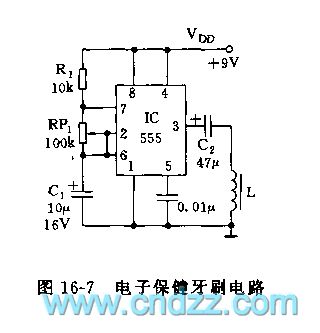
As the figure 16-7 shows, the health care toothbrush circuit uses the 555 to form a low frequency oscillator, f=1.44/(R1+RP1)C1.
The figure parameter's oscillation frequency is 1-20Hz, you can select the appropriate frequency of oscillation by adjusting RP1, the output drives an electromagnetic armature through the capacitor C2, and this circuit changes the output voltage into the small amplitude of mechanical vibration, and it drives the brush head to vibrate, clean, and massage the gum to promote the blood circulation and keep health.
(View)
View full Circuit Diagram | Comments | Reading(1286)
555 fall down SOS device circuit
Published:2011/5/24 2:54:00 Author:TaoXi | Keyword: fall down, SOS
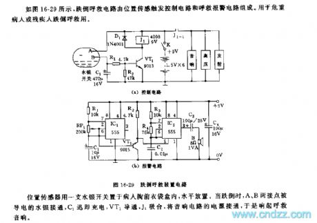
As the figure 16-29 shows, the fall down SOS device is composed of the position sensing trigger control circuit and the SOS alarm circuit. It can be used to help the critically ill patients or the disabled person.
The position sensor is in the patient's chest pocket, and it is horizontal. When the patient falls down, the contact points A and B are connected by the conductive mercury, C1 charges, VT1 conducts, J1 closes, and the speaker circuit power is connected.
The astable multivibrator is composed of the IC1 and R1,RP1,C1, the oscillation period T=1 second.
(View)
View full Circuit Diagram | Comments | Reading(712)
555 multifunction electronic acupoint detection and therapeutic equipment circuit
Published:2011/5/24 1:00:00 Author:TaoXi | Keyword: multifunction, electronic, acupoint detection, therapeutic equipment
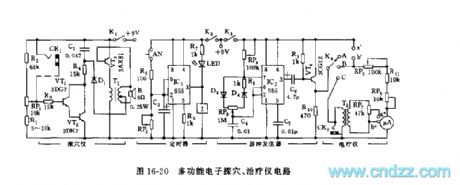
As the figure 16-20 shows, this multifunction electronic acupoint detection and therapeutic equipment circuit is composed of the acupoint detection circuit, the timer, the pulse generator and the amplifier output stage, it can be used in the acupoint detection and the no needle electrotherapy applications.
The acupoint detector is composed of the VT1,VT2,R1~R4,RP1,C1,VT3 and T1.etc, actually it is a audio oscillator. The timing circuit is composed of the IC1(555), R4,RP2 and C3. The astable multivibrator is composed of the IC2 and RP4,R8,D3,D4,RP3, C4, the oscillation frequency f=1.44/(RP4+RP3+R8)C4, the oscillation frequency and the duty ratio are adjustable.
(View)
View full Circuit Diagram | Comments | Reading(989)
| Pages:176/195 At 20161162163164165166167168169170171172173174175176177178179180Under 20 |
Circuit Categories
power supply circuit
Amplifier Circuit
Basic Circuit
LED and Light Circuit
Sensor Circuit
Signal Processing
Electrical Equipment Circuit
Control Circuit
Remote Control Circuit
A/D-D/A Converter Circuit
Audio Circuit
Measuring and Test Circuit
Communication Circuit
Computer-Related Circuit
555 Circuit
Automotive Circuit
Repairing Circuit