Signal Processing
The auto controller circuit of 555 fans
Published:2011/5/28 22:12:00 Author:Borg | Keyword: auto controller | From:SeekIC

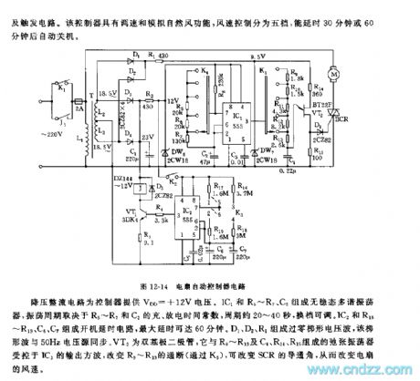
See as Figure 12-14, the controller includes the step-down rectifier circuit, low-frequency oscillator, timing circuit, controllable silicon conduction angle controller and trigger circuit. This controller has functions of speed adjusting and simulating natural wind, the wind speed is classified into 5 levels, and it can delay for 30min or 60min before the fan is power-off.
The step-down circuit offer the controller a voltage of +12V. IC1,R5~R7 and C2 consist a non-steady multi-resonate oscillator, whose oscillating period depends on the charging and discharging time parameters of R5~R7 and C2, the period ranges 20 to 40s which can be adjusted by shifting gears.
Reprinted Url Of This Article:
http://www.seekic.com/circuit_diagram/Signal_Processing/The_auto_controller_circuit_of_555_fans.html
Print this Page | Comments | Reading(3)

Article Categories
power supply circuit
Amplifier Circuit
Basic Circuit
LED and Light Circuit
Sensor Circuit
Signal Processing
Electrical Equipment Circuit
Control Circuit
Remote Control Circuit
A/D-D/A Converter Circuit
Audio Circuit
Measuring and Test Circuit
Communication Circuit
Computer-Related Circuit
555 Circuit
Automotive Circuit
Repairing Circuit
Code: