
Signal Processing
Index 170
LED dynamic display sequence generator circuit
Published:2011/6/7 19:13:00 Author:TaoXi | Keyword: LED, dynamic, display, sequence generator

The LED dynamic display sequence generator circuit is as shown in the figure 14-43, it is composed of the time-base oscillating circuit and the decimal count/pulse distributor, and it has a few of external components.
The multivibrator is composed of the 555 and R1, R2, RP1, C1, the oscillation frequency f=1.44/(R1+2R2+RP1)C1. The figure parameters' oscillation frequency is in the range of 2~14Hz, you can adjust RP1 to meet the dynamic changes of LED.
The IC2 uses the decimal count/pulse distributor CD4017, it's CP port (pin-14) is triggered by the pulse sequence jump on edge to count, and it outputs the Q0~Q9 high-level pulses in proper sequence (pulse width T=1/f), also it drives the corresponding LEDs to turn on in proper sequence.
(View)
View full Circuit Diagram | Comments | Reading(868)
555 DC sound erasing to AC sound erasing circuit
Published:2011/6/7 21:08:00 Author:TaoXi | Keyword: 555, DC, sound erasing, AC
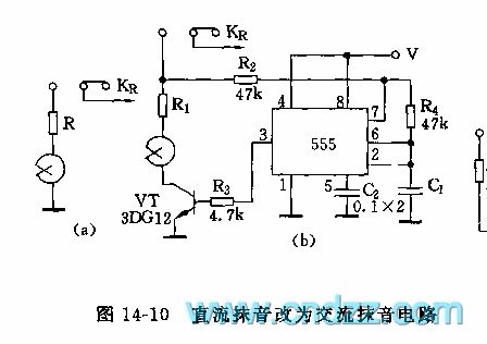
The general recorder uses the DC sound erasing mode, so the recording noise is large. Figure 14-10(a) is the DC sound erasing circuit. Figure(b) is the AC sound erasing circuit. The astable multivibrator is composed of the 555 and R4, C1, f=1.44/R4C1, the figure parameters' oscillation frequency is about 200Hz, the pin-3 outputs the driving amplifier to supply the sound erasing current to the sound erasing circuit.
(View)
View full Circuit Diagram | Comments | Reading(550)
555 audio-visual equipment automatic power switching circuit
Published:2011/6/7 20:17:00 Author:TaoXi | Keyword: 555, audio-visual, equipment, automatic, power switching
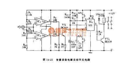
As the figure 14-21 shows, the power supply automatic switch is composed of the comparator, the OR gate circuit and the monostable delay circuit, and it can be used in the television and the recording equipments, when there is no sound over 2 minutes, the circuit will cut off the power supply automatically.
The comparative circuit is composed of the two operational amplifiers IC1 and IC2(uA741), the IC1's in-phase port pin-3 and the IC2's reversed-phase port connect with the reference level +6V, when the output signal of the televisions and the recording equipments is larger than +/-50mV, the comparator outputs the high electrical level, VT1 conducts, the capacitance C1 (the IC3's charging and discharging circuit) discharges, the 555's discharging port pin-7 has the low electrical level, the pin-3 has the high electrical level, VT2 conducts and J closes, the load gets the power to work.
(View)
View full Circuit Diagram | Comments | Reading(1441)
uPD550C (TV set) 4bit singlechip microprocessor circuit
Published:2011/6/6 9:31:00 Author:Lena | Keyword: 4bit, singlechip, microprocessor
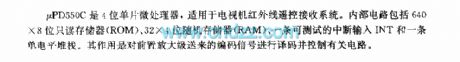
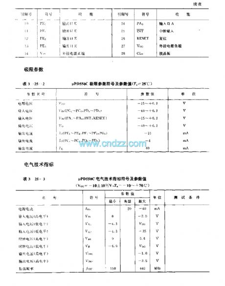
μPD550C is a 4-bit singlechip microprocessor applied to TV infrared remote control receiver system. Internal circuit includes 640×8bit real only memory(ROM), 32×4bit random access memory(RAM),a testable interrupt input INT and a single level stack. The function is encoding code signal sent by preamplifier and controlling related circuits.
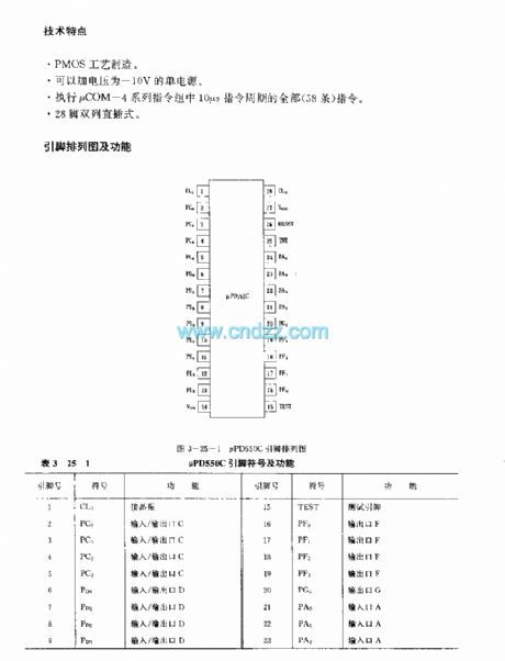
Technology characteristicPMOS technics.A -10V single power supply can be added.Execute all the instructions(58 pieces) that period is 10μs inμCOM-4 series team.
(View)
View full Circuit Diagram | Comments | Reading(987)
FCA84C640(TV) remote control microprocessor
Published:2011/6/8 10:18:00 Author:Lena | Keyword: remote control, microprocessor
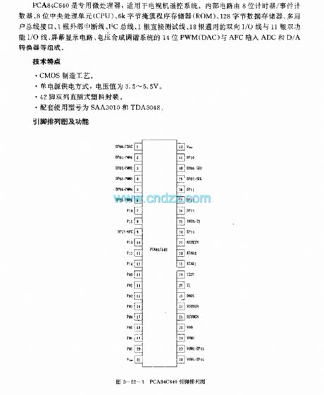
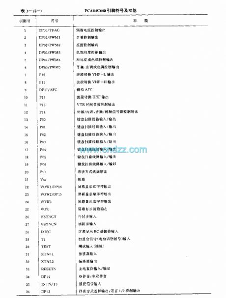
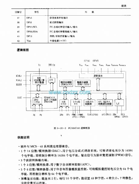
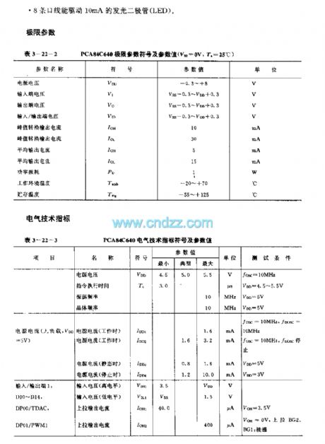
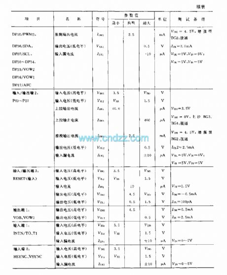
PCA84C640 is a special microprocessor applied to TV remote control system. Internal circuit consists of 8-bit counter/event counter, 8-bit central processing unit(CPU), 6k byte mask program memory(ROM), 128 byte data memory, multi-user bus line interface, 1 outside interrupt line, I2C bus line, 1 direct test line, 18 universal two-way I/O line and 11 two-function I/O line, screen display circuit, voltage synthesis tune system 14-bit PWM(DAC) and AFC input ADC and D/A converter etc.
(View)
View full Circuit Diagram | Comments | Reading(1132)
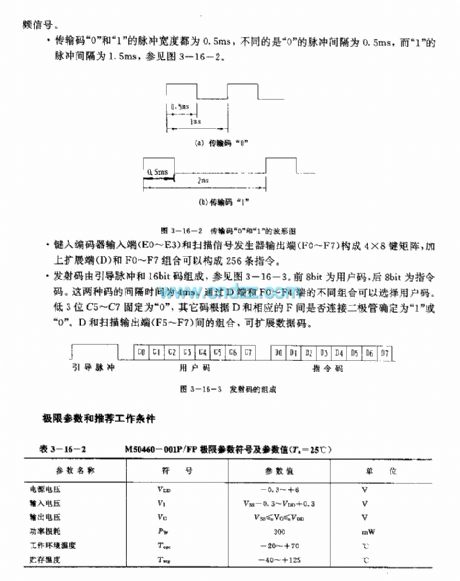
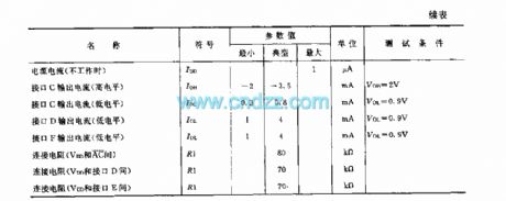
M50460—001P/FP (TV)infrared remote control transmitting microprocessor
Published:2011/6/1 9:37:00 Author:Lena | Keyword: infrared, remote control, transmitting, microprocessor
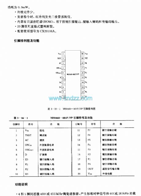
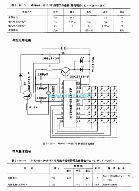
M50460-001P/FP are infrared remote control transmitting microprocessors used in TV etc. The only difference between M50460-001P and M50460-001FP is the shape.
technology features
Single voltage source, voltage range is 2.2 to 5.5V.Power loss is low. When at Readiness, typical power loss is 3nW,max loss is 3μW; at natural work, the max loss is 0.9mW.A few of external elements Transmitting signals, the infrared LED power loss is low.Internal circuit includes Read-only memory, used to control scan output, key input decode and transmission code output.20 pins dual in-line plastic package.
(View)
View full Circuit Diagram | Comments | Reading(658)
M491 (TV)infrared remote control receiving microprocessor
Published:2011/6/1 9:41:00 Author:Lena | Keyword: infrared, remote control, receiving, microprocessor
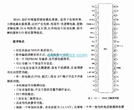
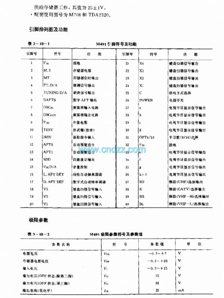
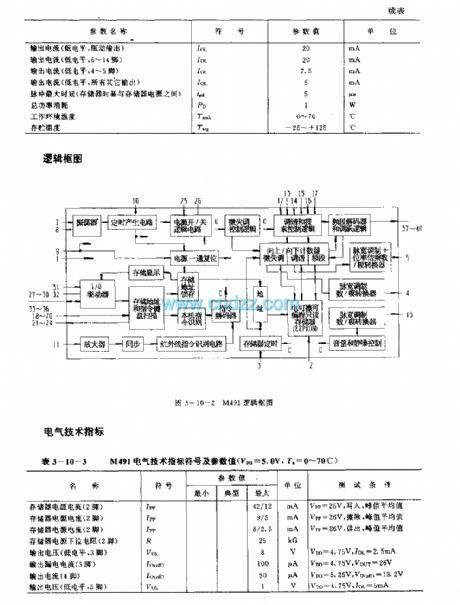
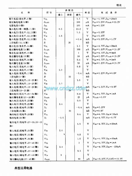
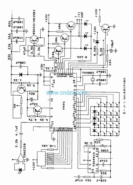
M491 is an infrared remote control receiving microprocessor applied to TV etc. Internal circuit is composed by oscillator, timing generating circuit, power supply on/off logic circuit, control logic circuit, D/A converter, amplifier, infrared instruction Identification circuit, instruction decoder and I /O driver etc.
Technical characteristictwo-poly silicon NMOS manufacturing Technologypulse code modulation transmitting method, duty cycle is 0.15%.A EEPROM memory, and simple external circuit.Store 16 preelection program information13-bit voltage synthesis tuner, which has three functions: manual tune, auto tune and auto preplace.
(View)
View full Circuit Diagram | Comments | Reading(1048)
M501245A(TV) infrared remote control receiving microprocessor
Published:2011/6/1 9:40:00 Author:Lena | Keyword: infrared, remote control, receiving, microprocessor
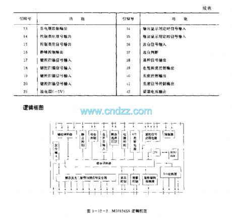
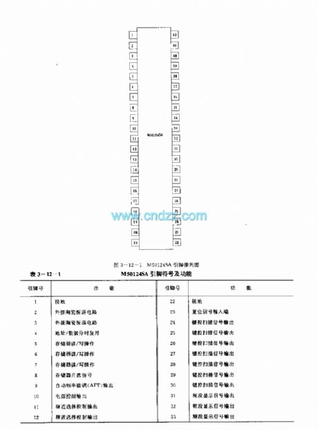
M50124SA is an infrared remote control receiving microprocessor which is applied to TV etc. Internal circuit is composed by oscillator, remote control signal processing circuit, AFT control circuit, power supply control circuit, channel selection control circuit, main switch input circuit, state control circuit, mute control circuit, key control decoder, reset input circuit, display control circuit, receiving code detector, CPU, ROM/RAM, D/A converter and instruction decoder etc. Package type is 42-pin dual-in-line plastic package.
(View)
View full Circuit Diagram | Comments | Reading(633)
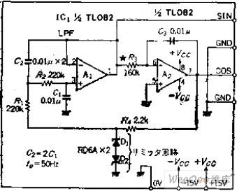
Waveform and Low Distortion SLF Two-phase Oscillation Circuit
Published:2011/6/5 8:06:00 Author:Michel | Keyword: Waveform, Low Distortion, SLF, Two-phase Oscillation Circuit
Circuit's Functions
The phase oscillator which can get SIN and COS waves is often used as AC motor signal generator and can also be used as signal source of orthogonal coordinate transformation and adopted as graphic display of X and Y monitor.This circuit is oscillation stability circuit without AGC loop and it can obtain oscillation output when it is low frequency.
Circuit's Work PrincipleOP amplifier,A1 constitutes level 2 low-pass filter,cutoff frequency's phase lags 90 degree, the amplitude is -3DB and integral circuit has nothing to do with the frequency.But it lags 270 degree,the whole circuit produces 360-degree phase shift. (View)
View full Circuit Diagram | Comments | Reading(707)
TMP47C433AN (TV set) microprocessor
Published:2011/6/6 8:48:00 Author:Lena | Keyword: microprocessor
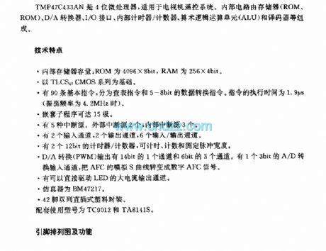
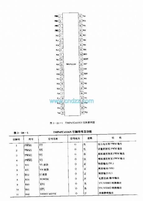
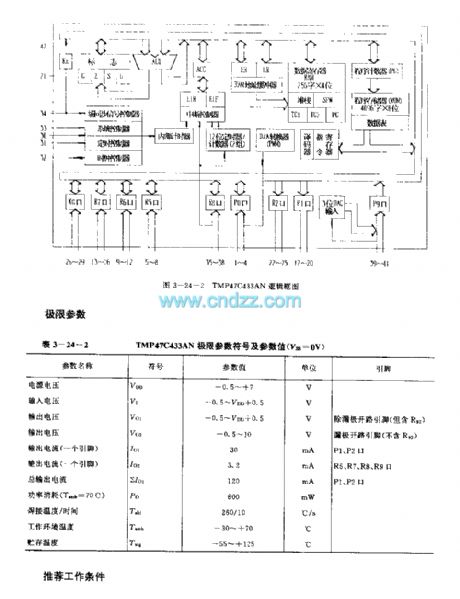

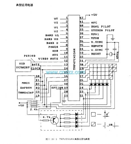
TMP47C433AN is a 4-bit microprocessor applied to TV remote control system. Internal circuit consists of memory(ROM、ROM),D/A converter, I/O interface, internal calculagraph /counter, arithmetic logic unit(ALU) and encoder etc.
Technology characteristicInternal memory capability: ROM is 4096×8bit,RAM is 256×4bit.Based on TLCS47CMOS series.Ninety basic instructions are classified to select table instructions and 5-8bit data convert instructions. Execution time is 1.9μs(oscillation frequency is 4.2MHz).
(View)
View full Circuit Diagram | Comments | Reading(1240)
450Hz Venturi bridge signal generator circuit
Published:2011/5/25 6:06:00 Author:Christina | Keyword: 450Hz, Venturi, bridge signal, generator
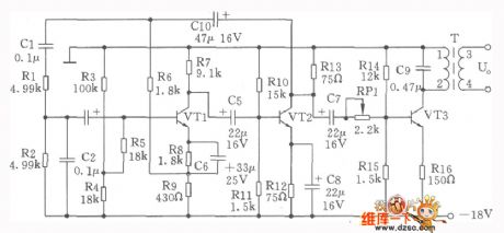
The 450Hz Venturi bridge signal generator circuit, also called the RC oscillator, the circuit is as shown. The oscillator is composed of the VTl, VT2, the feedback network Rl, R2 and the C1、C2. The negative feedback which is composed of the R6、R9 and Cl0 keeps the stabilization of the amplitude and the frequency. The transistor VTl's DC bias resistor are the R3, R4, R7, R8 and R9. The R5 is the input addition resistor, it improves the input impedance. The Rl0, Rll, Rl2 and Rl3 are the DC bias resistor of VT2. VT3 is the power output stage, the output signal gets through the frequency selection networks C9 and L1-2, then output by the transformer T's secondary stage L3-4. The transistor VTl~VT3:3DG128、β=50~70. The capacitor Cl, C2: CM0-100V-50000pF, the measurement error ±0.3%. The thermistor RT: RR527B uses the 2.2V, 12mA.
(View)
View full Circuit Diagram | Comments | Reading(837)
555 three colors flash light circuit
Published:2011/5/21 22:27:00 Author:TaoXi | Keyword: three colors, flash light

As the figure 17-49 shows, the circuit is composed of the 556 and a dual core light tube. The 2Hz multivibrator is composed of the IC's left part (1/2 556) and the R1,R2,C1.etc; The 0.5Hz multivibrator is composed of the IC's right part (1/2 556) and the R4,R5,C2.etc. The pin-5 and pin-9 of the output port drive the red diode and the green diode to turn on, so we have the three color flash (red, freen and orange), the brightness dazzles the eyes.
(View)
View full Circuit Diagram | Comments | Reading(536)
555 brightness adjustable indicator light circuit
Published:2011/5/21 9:33:00 Author:TaoXi | Keyword: brightness, adjustable, indicator light

In some conditions we need the brightness adjustable indicator light, if we uses the resistance step-down method, the power consumption is large. This circuit uses the variable duty cycle oscillation square-wave to supply power, this method can adjust the brightness of the light, and can save the power.
As the figure 17-42 shows, the astable multivibrator is composed of the 555 and R1,R2,RP1,C1. The oscillation periods are:
T=0.0693(R1+R2+RP1)C1t(charging)=0.693R2C1t(discharging)=0.0693(R1+RP1)C1
By adjusting RP1, we can change the t(discharging) which means the lighting time of the lamp.
(View)
View full Circuit Diagram | Comments | Reading(449)
555 mobile light program controller circuit
Published:2011/5/21 8:30:00 Author:TaoXi | Keyword: mobile light, program controller

As the figure 17-55 shows, the program controller is composed of the clock generation circuit, the logic circuit and the SCR control circuit.etc. And this circuit can be used in the program control of the advertising lights and mobile lights.
The astable multivibrator is composed of the 555 and R1,RP1,C1. The oscillation frequency is adjusted by the RP1, the frequency range is between 0.5Hz to 45Hz. And this astable multivibrator is used to control the logic control circuit's cycle.
The logic circuit is composed of the 4-D trigger 74LS175 and the switches such as AN1 and AN2. Every D trigger of 74LS175 has independent data input port D and output port Q. When you open the power supply switch K1, and the mode selection switch K2 is in the position 1 , and then you press AN1 to make K2 to 0, the output ports 1Q,2Q,3Q and 4Q all have the low level voltage.
(View)
View full Circuit Diagram | Comments | Reading(551)
555 simple printing phase timing circuit
Published:2011/5/21 6:18:00 Author:TaoXi | Keyword: simple, printing phase, timing circuit

As the figure 17-11 shows, the monostable delay circuit is composed of the 555 and RP1,C1.etc. Every time when you print, because the voltage of C2 can not abrupt change, as a negative pulse adds to the pin-2 of IC, 555 sets, J closes, the light turns on. At the same time, the timing begins. After C1 is charged to 2/3VDD, 555 reverses, pin-3 has the low level voltage, the timing is over. The delay time td=1.1RP1C1. The parameter's maximum delay time in the figure is about 5 seconds. You need to adjust RP1 to the appropriate printing phasetime.
(View)
View full Circuit Diagram | Comments | Reading(491)
555 simple exposure timer circuit
Published:2011/5/21 5:58:00 Author:TaoXi | Keyword: simple, exposure timer

As the figure 17-5 shows, the photo exposure timer circuit uses the 555 as the core. This circuit is one kind of artificially start monostable circuit. If you press AN, the timing capacitor C1 immediately discharges to zero, 555 sets, the timing begins, J closes, the light H turns on. The lighting time is the time of C1 charges to 2/3VDD td=1.1(R1+RP1)C1. The length of time can be set by the photo typy. When the time is up, 555 returns to the reset state, pin-3 has the low level voltage, J releases, H turns off automaticly. The parameter's td in the figure is about 2 minutes.
(View)
View full Circuit Diagram | Comments | Reading(869)
555 simple seven color lamp circulation control circuit
Published:2011/5/21 5:05:00 Author:TaoXi | Keyword: simple, seven color lamp, circulation control
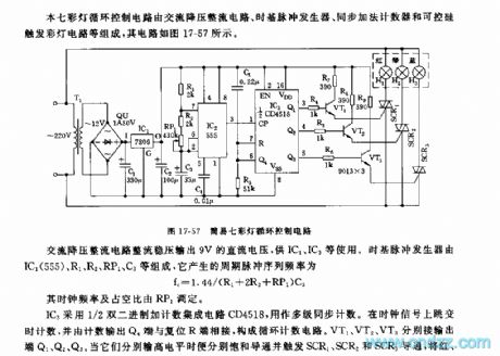
This seven color lamp circulation control circuit is composed of the DC step-down rectifier circuit, the time base pulse generator, the synchronous addition counter and the SCR trigger color light circuit, the circuit is as shown in figure 17-57.
The IC3 uses the 1/2 double binary adding & counting integrated circuit CD4518 as the multi-level synchronous counter. If you jump the time counting on the clock signal and connect the counting output terminal Q4 with the reset terminal R, so you constitute the circulation technology circuit. VT1, VT2, VT3 respectively connect to the output port Q1,Q2,Q3. The alterable colour unit is composed of the red, green, blue gezer lamp.
(View)
View full Circuit Diagram | Comments | Reading(442)
555 "happy birthday to you" electronic candle circuit
Published:2011/5/22 3:09:00 Author:TaoXi | Keyword: happy birthday to you, electronic candle
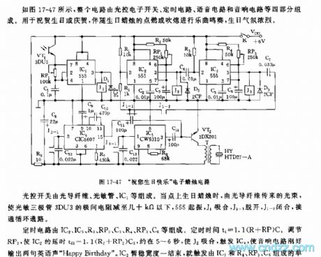
As the figure 17-47 shows, the whole circuit is composed of four parts: the optical electronic switch, the timing circuit, the voice circuit and the audio circuit, and it can be used in applications of birthday congratulation or celebration.
The optical switch is composed of the optical fiber, the light sensitive tube and the IC1.etc. When you light up the birthday candle, the light beam which is transmitted by the optical fiber reduces the interelectrode resistance of the phototransistor 3DU3 lower than dozens of ohms, 555 starts up, J1 closes, J1-1 turns off and J1-2 closes, the circulation path is connected.
The timing circuit is composed of the IC2,IC3,R2,RP2,C3,R4,RP3,C5. The timing time td=1.1(R+RP)C.
(View)
View full Circuit Diagram | Comments | Reading(1310)
555 toilet floodlight and ventilator automatic control circuit
Published:2011/5/21 4:32:00 Author:TaoXi | Keyword: toilet floodlight, ventilator, automatic control

The electronic switch is composed of the CK-4 type magnetic control switch and the VT1,R1,R2. When the bathroom door closes, the permanent magnet ZT and the reed pipe GA get close to separate the two touch tablets of GA, VT1 cuts off, pin-2 of IC has the high level voltage, 555 is in the reset state, J releases, the ventilation fan and light has no power. When someone gets into the bathroom and opens the door, the ZT and GA are seperated, VT1 conducts, 555 sets, J closes to close the J1-1 and J1-2, the ventilation fan gets the power to work, the light turns on. The power-on time depends on the delay time of the 555 homeostasis circuit td=1.1R3C2, the parameter in the figure is about 1 minute, you can change it by changing the R3C2 time constant.
(View)
View full Circuit Diagram | Comments | Reading(1277)
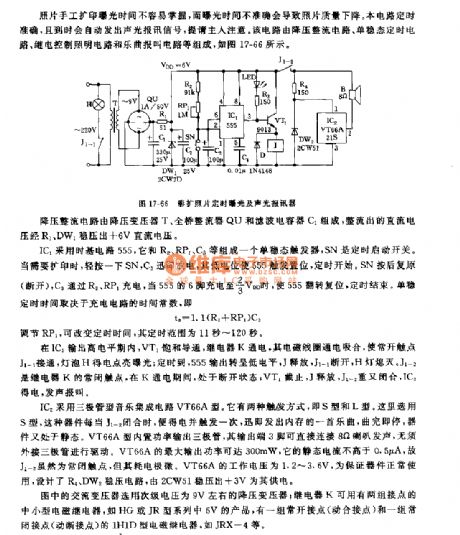
555 color amplification photo time exposure and acousto-optic alarm device
Published:2011/5/24 2:51:00 Author:TaoXi | Keyword: color amplification, photo, time exposure, acousto-optic, alarm
Related components PDF download:
NE555VT66A21S9013
IC2 uses the audion type music IC VT66A. It has two kind of trigger mode: S mode and L mode. Here we use the S mode, this device will get the electricity and trigger for one time if the J1-2 closes, it sends out a song in the memory, after playing, this device will be in the static. The VT66A mode has the built-in power output transistor, the output port pin-3 can be connected with the 8 ohm speaker to send out voice, and there is no need to connect the external audion to drive. VT66A's maximum output power is 300mW, it's static current is less than 0.5 uA.
(View)
View full Circuit Diagram | Comments | Reading(437)
| Pages:170/195 At 20161162163164165166167168169170171172173174175176177178179180Under 20 |
Circuit Categories
power supply circuit
Amplifier Circuit
Basic Circuit
LED and Light Circuit
Sensor Circuit
Signal Processing
Electrical Equipment Circuit
Control Circuit
Remote Control Circuit
A/D-D/A Converter Circuit
Audio Circuit
Measuring and Test Circuit
Communication Circuit
Computer-Related Circuit
555 Circuit
Automotive Circuit
Repairing Circuit